

Week 8: Fluids |
|
363 |
||
these two equations by one another to eliminate the V : |
|
|||
|
Tw |
= |
ρcrown − ρwater |
(748) |
|
ρcrown |
|||
|
Ta |
|
||
Whoa! g went away too! This means that from here on we don’t even care what g is – we could make these weight measurements on the moon or on mars and we’d still get the relative density of the crown (compared to the density of water) right!
A bit of algebra-fu: |
|
|
|
|
Tw |
|
|
|
|
Ta − Tw |
|
ρ |
|
= ρ |
(1 |
− |
) = ρ |
|
|
(749) |
|||
|
Ta |
|
|
Ta |
|||||||
|
water |
crown |
|
|
|
crown |
|
||||
or finally: |
|
|
|
|
|
|
Ta |
|
|
||
|
|
ρcrown = ρwater |
|
(750) |
|||||||
|
|
Ta − Tw |
|
|
|||||||
We are now prepared to be precise. Suppose that the color of the crown is very good. We perform the measurements above (using a scale accurate to better than a hundredth of a Newton or we might end up condemning our goldsmith due to a measurement error! ) and find that Ta = 10.00 Newtons, Tw = 9.45 Newtons. Then
ρcrown = 1000 |
10.00 |
= 18182 kilograms/meter3 |
(751) |
|
|||
|
|||
|
10.00 − 9.45 |
|
|
We subtract, 19300 −18182 = 1118; divide, 1118/19300 ×100 = 6%. Our crown’s material is around six percent less dense than gold which means that our clever goldsmith has adulterated the gold by removing some 12% of the gold (give or take a percent) and replace it with some mixture of silver and copper. Baaaaad goldsmith, bad.
If the goldsmith were smart, of course, he could have beaten Archimedes (and us). What he needed to do is adulterate the gold with a mixture of metals that have exactly the same density as gold! Not so easy to do, but tungsten’s density, ρW = 19300 (to three digits) almost exactly matches that of gold. Alas, it has the highest melting point of all metals at 3684◦K, is enormously hard, and might or might not alloy with gold or change the color of the gold if alloyed. It is also pretty expensive in its own right. Platinum, Plutonium, Iridium, and Osmium are all even denser then gold, but three of these are very expensive (even more expensive than gold!) and one is very explosive, a transuranic compound used to make nuclear bombs, enormously expensive and illegal to manufacture or own (and rather toxic as well). Not so easy, matching the density via adulteration and making a profit out of it...
Enough of all of this fluid statics. Time to return to some dynamics.
8.4: Fluid Flow
In figure 111 we see fluid flowing from left to right in a circular pipe. The pipe is assumed to be “frictionless” for the time being – to exert no drag force on the fluid flowing within – and hence all of the fluid is moving uniformly (at the same speed v with no relative internal motion) in a state of dynamic equilibrium.
We are interested in understanding the flow or current of water carried by the pipe, which we will define to be the volume per unit time that passes any given point in the pipe. Note well that we could instead talk about the mass per unit time that passes a point, but this is just the volume per unit time times the density and hence for fluids with a more or less uniform density the two are the same within a constant.
For this reason we will restrict our discussion in the following to incompressible fluids, with constant ρ. This means that the concepts we develop will work gangbusters well for understanding
364 |
Week 8: Fluids |
V
A
v
v t
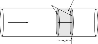
Figure 111: Fluid in uniform flow is transported down a pipe with a constant cross-section at a constant speed v. From this we can easily compute the flow, the volume per unit time that passes (through a surface that cuts the pipe at) a point on the pipe.
water flowing in pipes, beer flowing from kegs, blood flowing in veins, and even rivers flowing slowly in not-too-rocky river beds but not so well to describe the dynamical evolution of weather patterns or the movement of oceanic currents. The ideas will still be extensible, but future climatologists or oceanographers will have to work a bit harder to understand the correct theory when dealing the compressibility.
We expect a “big pipe” (one with a large cross-sectional area) to carry more fluid per unit time, all other things being equal, than a “small pipe”. To understand the relationship between area, speed and flow we turn our attention to figure 111. In a time t, all of the water within a distance v t to the left of the second shaded surface (which is strictly imaginary – there is nothing actually in that pipe at that point but fluid) will pass through this surface and hence past the point indicated by the arrow underneath. The volume of this fluid is just the area of the surface times the height of the cylinder of water:
V = Av t |
(752) |
|||
If we divide out the t, we get: |
|
|
|
|
I = |
V |
= Av |
(753) |
|
t |
||||
|
|
|
||
This, then is the flow, or volumetric current of fluid in the pipe.
This is an extremely important relation, but the picture and derivation itself is arguably even more important, as this is the first time – but not the last time – you have seen it, and it will be a crucial part of understanding things like flux and electric current in the second semester of this course. Physics and math majors will want to consider what happens when they take the quantity v and make it a vector field ~v that might not be flowing uniformly in the pipe, which might not have a uniform shape or cross section, and thence think still more generally to fluids flowing in arbitrary streamlined patterns. Future physicians, however, can draw a graceful curtain across these meditations for the moment, although they too will benefit next semester if they at least try to think about them now.
8.4.1: Conservation of Flow
Fluid does not, of course, only flow in smooth pipes with a single cross-sectional area. Sometimes it flows from large pipes into smaller ones or vice versa. We will now proceed to derive an important aspect of that flow for incompressible fluids and/or steady state flows of compressible ones.
Figure 112 shows a fluid as it flows from just such a wider pipe down a gently sloping neck into a narrower one. As before, we will ignore drag forces and assume that the flow is as uniform as possible
Week 8: Fluids |
365 |
V
A1
A 2
P1
|
P2 |
|
V (constant) |
v2 |
|
v1 |
||
|
||
|
v2 t |
|
v1 t |
2 |
|
|
||
1 |
|
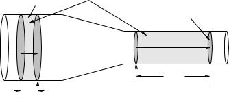
Figure 112: Water flows from a wider pipe with a “larger” cros-sectional area A1 into a narrower pipe with a smaller cross-sectional area A2. The speed of the fluid in the wider pipe is v1, in the narrower one it is v2. The pressure in the wider pipe is P1, in the narrower one it is P2.
as it narrows, while remaining completely uniform in the wider pipe and smaller pipe on either side of the neck. The pressure, speed of the (presumed incompressible) fluid, and cross sectional area for either pipe are P1, v1, and A1 in the wider one and P2, v2, and A2 in the narrower one.
Pay careful attention to the following reasoning. In a time t then – as before – a volume of fluid V = A1v1 t passes through the surface/past the point 1 marked with an arrow in the figure. In the volume between this surface and the next grey surface at the point 2 marked with an arrow no fluid can build up so actual quantity of mass in this volume must be a constant.
This is very important. The argument is simple. If more fluid flowed into this volume through the first surface than escaped through the second one, then fluid would be building up in the volume. This would increase the density. But the fluid’s density cannot change – it is (by hypothesis) incompressible. Nor can more fluid escape through the second surface than enters through the first one.
Note well that this assertion implies that the fluid itself cannot be created or destroyed, it can only flow into the volume through one surface and out through another, and because it is incompressible and uniform and the walls of the vessel are impermeable (don’t leak) the quantity of fluid inside the surface cannot change in any other way.
This is a kind of conservation law which, for a continuous fluid or similar medium, is called a continuity equation. In particular, we are postulating the law of conservation of matter, implying a continuous flow of matter from one place to another! Strictly speaking, continuity alone would permit fluid to build up in between the surfaces (as this can be managed without creating or destroying the mass of the fluid) but we’ve trumped that by insisting that the fluid be incompressible.
This means that however much fluid enters on the left must exit on the right in the time |
t; |
the shaded volumes on the left and right in the figure above must be equal. If we write this |
out |
algebraically: |
|
|
|
|
|
V = A1v1 |
t = A2v2 |
t |
|
I = |
V |
|
|
|
|
= A1v1 |
= A2v2 |
(754) |
|
|
||||
|
t |
|
|
|
Thus the current or flow through the two surfaces marked 1 and 2 must be the same:
A1v1 = A2v2 |
(755) |
Obviously, this argument would continue to work if it necked down (or up) further into a pipe with cross sectional area A3, where it had speed v3 and pressure P3, and so on. The flow of water in the pipe must be uniform, I = Av must be a constant independent of where you are in the pipe!
Week 8: Fluids |
367 |
8.4.2: Work-Mechanical Energy in Fluids: Bernoulli’s Equation
Daniel Bernoulli was a third generation member of the famous Bernoulli family157 who worked on (among many other things) fluid dynamics, along with his good friend and contemporary, Leonhard Euler. In 1738 he published a long work wherein he developed the idea of energy conservation to fluid motion. We’ll try to manage it in a page or so.
|
|
A |
|
V P |
|
|
|
2 |
F2 |
2 |
|
|
|
|
|
|
|
|
|
|
|
v |
2 |
|
|
|
|
D |
|
|
|
|
|
y2 |
|
|
V A1 |
|
|
|
|
|
F1 |
|
|
|
|
P1 |
v1 |
y |
|
|
|
|
1 |
|
|
||
|
|
|
|
|
|
|
d |
|
|
|
|
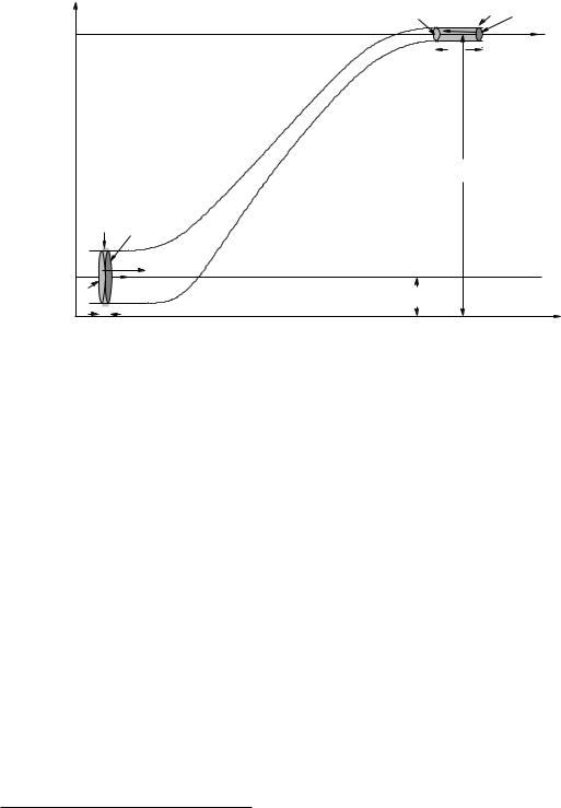
Figure 113: A circular cross-sectional necked pipe is arranged so that the pipe changes height between the larger and smaller sections. We will assume that both pipe segments are narrow compared to the height change, so that we don’t have to account for a potential energy di erence (per unit volume) between water flowing at the top of a pipe compared to the bottom, but for ease of viewing we do not draw the picture that way.
In figure 113 we see the same pipe we used to discuss conservation of flow, only now it is bent uphill so the 1 and 2 sections of the pipe are at heights y1 and y2 respectively. This really is the only change, otherwise we will recapitulate the same reasoning. The fluid is incompressible and the pipe itself does not leak, so fluid cannot build up between the bottom and the top. As the fluid on the bottom moves to the left a distance d (which might be v1 t but we don’t insist on it as rates will not be important in our result) exactly the same amount fluid must move to the left a distance D up at the top so that fluid is conserved.
The total mechanical consequence of this movement is thus the disappearance of a chunk of fluid mass:
m = ρ V = ρA1d = ρA2D |
(756) |
that is moving at speed v1 and at height y1 at the bottom and it’s appearance moving at speed v2 and at height y2 at the top. Clearly both the kinetic energy and the potential energy of this chunk of mass have changed.
What caused this change in mechanical energy? Well, it can only be work. What does the work? The walls of the (frictionless, drag free) pipe can do no work as the only force it exerts is perpendicular to the wall and hence to ~v in the fluid. The only thing left is the pressure that acts on the entire block of water between the first surface (lightly shaded) drawn at both the top and
157Wikipedia: http://www.wikipedia.org/wiki/Bernoulli family. The Bernoullis were in on many of major mathematical and physical discoveries of the eighteenth and nineteenth century. Calculus, number theory, polynomial algebra, probability and statistics, fluid dynamics – if a theorem, distribution, principle has the name “Bernoulli” on it, it’s gotta be good...