


294 |
Week 6: Vector Torque and Angular Momentum |
this point in the course you have no doubt gotten much better at math and have started to overcome your fears – there is no need to charge you points for wading through stu I could make a mistake doing almost as easily as you could. If anything, we’ll give you extra points if you try it and succeed
– after giving us something clear and correct to grade for primary credit first!
Finally, we do need to compute the kinetic energy lost in the collision:
K = Kf − Ki = |
Lf2 |
+ |
1 |
(m + M )vf2 − |
1 |
mv02 |
(608) |
2If |
2 |
2 |
is as easy a form as any. Here there may be some point to squaring everything out to simplify, as one expects an answer that should be “some fraction of Ki”, and the value of the fraction might be interesting. Again, if you are a physics major you should probably do the full simplification just for practice doing lots of tedious algebra without fear, useful self-discipline. Everybody else that does it will likely get extra credit unless the problem explicitly calls for it.
Now, let’s do the whole thing over, using a di erent pivot, and see where things are the same and where they are di erent.
Using the end of the rod:
Obviously there is no change in the computation of xcm and vf – indeed, we really did these in the (given) coordinate frame starting at the end of the rod anyway – that’s the “lab” frame drawn into our figure and the one wherein our answer is finally expressed. All we need to do, then, is compute our angular momenta relative to an origin/pivot at the end of the rod:
Li = |~r × p~| = r mv0 = mv0L |
(609) |
and: |
|
Lf = (m + M )vf xcm + If ωf |
(610) |
In this final expression, (m + M )vf xcm is the angular momentum of the entire system treated as a mass moving at speed vf located at xcm right after the collision, plus the angular momentum of the system around the center of mass, which must be computed exactly as before, same If , same ωf (to be found). Thus:
If ωf = mv0L − (m + M )vf xcm |
(611) |
Here is a case where one really must do a bit more simplification – there are just too many things that depend on the initial conditions. If we substitute in vf from above, in particular, we get:
|
If ωf = mv0L − mv0xcm = mv0(L − xcm) |
(612) |
||||
and: |
mv0(L − xcm) |
|
|
|
mv0(L − xcm) |
|
ωf = |
= |
|
1 |
(613) |
||
|
|
M L2 + M (xcm − L/2)2 + m(L − xcm)2 |
||||
|
If |
|
|
|||
|
|
12 |
|
|||
as before. The algebra somehow manages the frame change for us, giving us an answer that doesn’t depend on the particular choice of frame once we account for the angular momentum of the center of mass in any frame with a pivot that isn’t on the line of motion of xcm (where it is zero). Obviously, computing K is the same, and so we are done!. Same answer, two di erent frames!
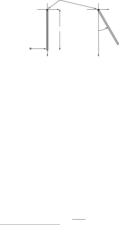
Example 6.5.2: Fully Inelastic Collision of Ball of Putty with Pivoted Rod
In figure 87 we see the alternative version of the fully inelastic collision between a pivoted rod and a blob of putty. Let us consider the answers to the questions in the previous problem. Some of them will either be exactly the same or in some sense “irrelevant” in the case of a pivoted rod, but either way we need to understand that.
 m
m
Week 6: Vector Torque and Angular Momentum |
297 |
z
ω
v
m |
|
r |
τ |
θ |
|
|
|
L |
|
y |
|
x |
Figure 88: A point mass m at the end of a massless rod that makes a vector ~r from the origin to the location of the mass, moving at constant speed v sweeps out a circular path of radius r sin(θ) in a plane above the (point) pivot. The angular momentum of this mass is (at the instant shown)
~ |
~ |
L = ~r×m~v = ~r×p~ as shown. As the particle sweeps out a circle, so does L! The extended massless |
|
rigid rod exerts a constantly changing/precessing torque ~τ |
on the mass in order to accomplish this. |
which points up and to the left at the instant shown in figure 88.
~ |
|
|
Note well that L is perpendicular to both the plane containing ~r and ~v, and that as the mass |
||
~ |
~ |
|
moves around in a circle, so does L! In fact the vector L sweeps out a cone, just as the vector |
||
|
~ |
|
~r does. Finally, note that the magnitude of L has the constant value: |
|
|
|
L = |~r × ~v| = mvr |
(622) |
because ~r and ~v are mutually perpendicular.
~ ~
This means, of course, that although L = |L| is constant, L is constantly changing in time. Also,
~
we know that the time rate of change of L is ~τ, so the rod must be exerting a nonzero torque on the mass! Finally, the scalar moment of inertia I = Izz = mr2 sin2(θ) for this rotation is a constant
~
(and so is ω~) – manifestly L 6= Iω~! They don’t even point in the same direction!
Consider the following physics. We know that the actual magnitude and direction the force acting on m at the instant drawn is precisely Fc = mv2/(r sin(θ) (in towards the axis of rotation) because the mass m is moving in a circle. This force must be exerted by the massless rod because there is nothing else touching the mass (and we are neglecting gravity, drag, and all that). In turn, this force must be transmitted by the rod back to a bearing of some sort located at the origin, that keeps the rod from twisting out to rotate the mass in the same plane as the pivot (it’s “natural” state of rigid rotation).
The rod exerts a torque on the mass of magnitude:
~ |
2 cos(θ) |
2 |
|
2 |
|
|
|
τrod = |~r × F c| = r cos(θ)Fc = mv |
|
sin(θ) |
= mω |
r |
|
sin(θ) cos(θ) |
(623) |
Now, let’s see how this compares to the total change in angular momentum per unit time. Note
~
that the magnitude of L, L, does not change in time, nor does Lz , the component parallel to the z-axis. Only the component in the x-y plane changes, and that components sweeps out a circle!
The radius of the circle is L = L cos(θ) (from examining the various right triangles in the figure)
~
and hence the total change in L in one revolution is:
L = 2πL = 2πL cos(θ) |
(624) |
This change occurs in a time interval t = T , the period of rotation of the mass m. The period of
298 |
Week 6: Vector Torque and Angular Momentum |
rotation of m is the distance it travels (circumference of the circle of motion) divided by its speed:
|
|
|
|
T = |
2πr sin(θ) |
|
|
(625) |
||
|
|
|
|
v |
|
|||||
|
|
|
|
|
|
|
|
|||
Thus the magnitude of the torque exerted over t = T is (using L = mvr as well): |
|
|||||||||
|
L |
= 2πL cos(θ) |
v |
= mv2 |
cos(θ) |
= mω2r2 sin(θ) cos(θ) |
(626) |
|||
|
t |
|
2πr sin(θ) |
sin(θ) |
||||||
|
|
|
|
|
|
|||||
so that indeed,
~τrod = |
L |
|
|
(627) |
|
|
||
|
t |
|
for the cycle of motion.
The rod must indeed exert a constantly changing torque on the rod, a torque that remains perpendicular to the angular momentum vector at all times. The particle itself, the angular momentum, and the torque acting on the angular momentum all precess around the z-axis with a
~
period of revolution of T and clearly at no time is it true that L = Iω~ for any scalar I and constant
ω~.
|
|
z |
|
|
|
ω |
|
z |
|
v |
|
ω |
v |
m |
|
m |
|
||
m |
L tot |
||
v |
|||
|
|
r |
|
Ltot |
r |
|
|
r |
L |
||
|
L |
||
|
L |
y |
|
L |
|
||
|
y |
r |
|
|
x |
||
|
|
||
x |
|
v |
|
|
|
||
|
|
m |
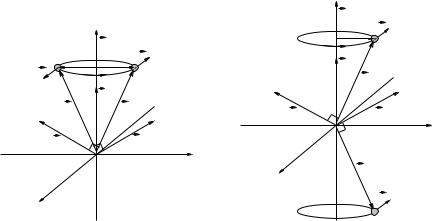
Figure 89: When the two masses have mirror symmetry across the axis of rotation, their
~
total angular momentum L does line up with ω~. When the two masses have mirror symmetry
~
across the plane of rotation, their total angular momentum L also lines up with ω~.
Notice how things change if we balance the mass with a second one on an opposing rod as drawn in figure 89, making the distribution mirror symmetric across the axis of rotation. Now each of the two masses has a torque acting on it due to the rod connecting it with the origin, each mass
~
has a vector angular momentum that at right angles to both ~r and ~v, but the components of L in the x-y plane phcancel so that the total angular momentum once again lines up with the z-axis!
The same thing happens if we add a second mass at the mirror-symmetric position below the plane of rotation as shown in the second panel of figure 89. In this case as well the components of
~
L in the x-y plane cancel while the z components add, producing a total vector angular momentum that points in the z-direction, parallel to ω~.
The two ways of balancing a mass point around a pivot are not quite equivalent. In the first case, the pivot axis passes through the center of mass of the system, and the rotation can be maintained without any external force as well as torque. In the second case, however, the center of mass of the system itself is moving in a circle (in the plane of rotation). Consequently, while no net external torque is required to maintain the motion, there is a net external force required to maintain the motion. We will di erentiate between these two cases below in an everyday example where they matter.