

Week 7: Statics |
|
|
|
319 |
By now the idea should be sinking in. Static equilibrium requires |
|
~ |
~τ = 0. There |
|
|
F = 0 and |
|||
are no forces in the z direction so we ignore it. There is only |
torque in the +z direction. In this |
|||
|
P |
|
P |
|
problem there is a clearly-best pivot to choose – one at the point of contact with the wall, where the two forces Fx and Fy are exerted. If we choose this as our pivot, these forces will not contribute to the net torque!
Thus: |
|
|
|
Fx − T cos(θ) |
= |
0 |
(658) |
Fy + T sin(θ) − mg |
= |
0 |
(659) |
T sin(θ)L − mgL/2 |
= |
0 |
(660) |
The last equation involves only T , so we solve it for:
T = |
mg |
(661) |
2 sin(θ) |
We can substitute this into the first equation and solve for Fx:
Fx = |
1 |
mg cot(θ) |
(662) |
||||||
|
|||||||||
2 |
|||||||||
Ditto for the second equation: |
|
|
1 |
|
1 |
|
|
||
Fy = mg − |
mg = |
mg |
(663) |
||||||
|
|
|
|||||||
2 |
2 |
||||||||
There are several features of interest in this solution. One is that the wire and the wall support each must support half of the weight of the sign. However, in order to accomplish this, the tension
in the wire will be strictly greater than half the weight!
√
Consider θ = 30◦. Then T = mg (the entire weight of the sign) and Fx = 23 mg. The magnitude of the force exerted by the wall on the pole equals the tension.
Consider θ = 10◦. Now T ≈ 2.9mg (which still must equal the magnitude of the force exerted by the wall. Why?). The smaller the angle, the larger the tension (and force exerted by/on the wall). Make the angle too small, and your pole will punch right through the brick wall!
7.2.1: Equilibrium with a Vector Torque
So far we’ve only treated problems where all of the forces and moment arms live in a single plane (if not in a single direction). What if the moment arms themselves live in a plane? What if the forces exert torques in di erent directions?
Nothing changes a whole lot, actually. One simply has to set each component of the force and torque to zero separately. If anything, it may give us more equations to work with, and hence the ability to deal with more unknowns, at the cost of – naturally – some algebraic complexity.
Static equilibrium problems involving multiple torque directions are actually rather common. Every time you sit in a chair, every time food is placed on a table, the legs increase the forces they supply to the seat to maintain force and torque equilibrium. In fact, every time any two-dimensional sheet of mass, such as a floor, a roof, a tray, a table is suspended horizontally, one must solve a problem in vector torque to keep it from rotating around any of the axes in the plane.
We don’t need to solve the most algebraically complex problems in the Universe in order to learn how to balance both multiple force components and multiple torque components, but we do need to do one or two to get the idea, because nearly everybody who is taking this course needs to be able to actually work with static equilibrium in multiple dimensions. Physicists need to be able to understand it both to teach it and to prime themselves for the full-blown theory of angular
320 |
Week 7: Statics |
momentum in a more advanced course. Engineers, well, we don’t want those roofs to tip over, those bridges to fall down. Physicians and veterinarians – balancing human or animal bodies so that they don’t tip over one way or another seems like a good idea. Things like canes, four point walkers, special support shoes all are tools you may one day use to help patients retain the precious ability to navigate the world in an otherwise precarious vertical static equilibrium.
Example 7.2.4: Building a Deck
F |
L = 6 |
F = 0 |
|
||
2 |
|
3 |
|
Mg (down/in) |
|
W = 4 |
|
|
1 |
|
|
F |
mg (down/in) |
F |
1 |
4 |
|
|
1 |
|
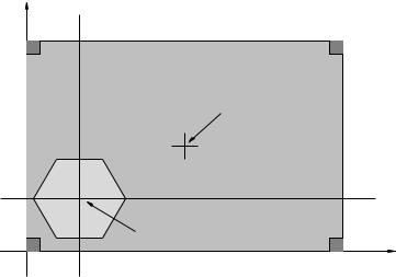
Figure 96:
In figure 96 a very simple deck layout is shown. The deck is 4 meters wide and 6 meters long. It is supported by four load-bearing posts, one at each corner. You would like to put a hot tub on the deck, one that has a loaded mass of m = 2000 kg, so that its center of mass is 1 meter in and 1 meter up from the lower left corner (as drawn) next to the house. The deck itself is a uniform concrete slab of mass M = 4000 kg with its center of mass is at (3,2) from the lower left corner.
You would like to know if putting the hot tub on the deck will exceed the safe load capacity of the nearest corner support. It seems to you that as it is loaded with the hot tub, it will actually reduce the load on F3. So find F1, F2, and F4 when the deck is loaded in this way, assuming a perfectly rigid plane deck and F3 = 0.
First of all, we need to choose a pivot, and I’ve chosen a fairly obvious one – the lower left corner, where the x axis runs through F1 and F4 and the y axis runs through F1 and F2.
Second, we need to note that |
Fx and Fy can be ignored – there are no lateral forces at all |
masses down, the corner beams push the deck itself up. We can |
|
at work here. Gravity pulls the P |
P |
solve the normal force and force transfer in our heads – supporting the hot tub, the deck experiences a force equal to the weight of the hot tub right below the center of mass of the hot tub.
This gives us only one force equation:
F1 + F2 + F4 − mg − M g = 0 |
(664) |
That is, yes, the three pillars we’ve selected must support the total weight of the hot tub and deck together, since the F3 pillar refuses to help out.
It gives us two torque equations, as hopefully it is obvious that τz = 0! To make this nice and algebraic, we will set hx = 1, hy = 1 as the position of the hot tub, and use L/2 and W/2 as the