


Virtuoso AMS Environment User Guide
Producing Customized Netlists
Example: Using Symbols that Represent Verilog Test Code
The goal in this example is to place a symbol representing a piece of Verilog test code in a schematic, and to have the test code inserted into the netlist. The symbol, which has no pins, is just a vehicle for the test code.
There are several steps involved in setting up for this approach.
1.Prepare a cellview that contains the test code. For this example, assume that the full name of the cellview is NetlistLib.verinc:verilog_include and that the following test code is in a file calledverilog.v in that cellview.
//--- begin included file ---
//Design debugger/monitor
parameter TCOff=0;
‘ifdef CHECK_INPUT_TRANSITIONS
always @(posedge(TCOff||in_d) or negedge(TCOff||in_d)) if (eval==1’b1)
$display($stime," WARNING: %m in_d transition (evaluate is active)");
always @(posedge(TCOff||out_y) or negedge(TCOff||out_y)) if (eval==1’b1)
$display($stime," INFO: %m out_y transition (evaluate is active)");
‘endif
// ---- end of included file ----
Ultimately, this code is written into the netlist so that if the CHECK_INPUT_TRANSITION variable is set, the code checks the transitions.
April 2004 |
318 |
Product Version 5.3 |
Virtuoso AMS Environment User Guide
Producing Customized Netlists
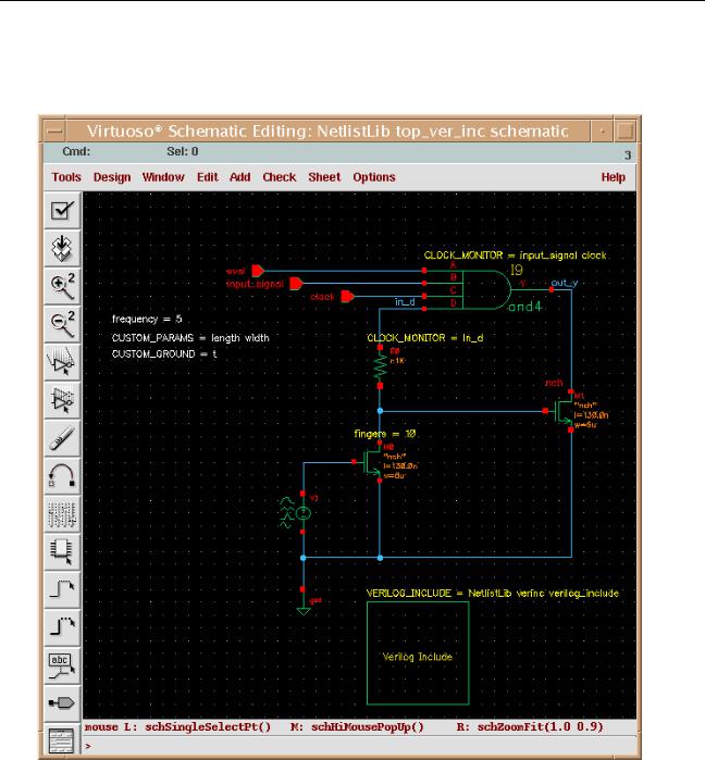
2.Create a symbol and place it in the schematic whose netlist is to contain the test code.
In the following schematic, for example, notice the simple square symbol labeled
Verilog Include.
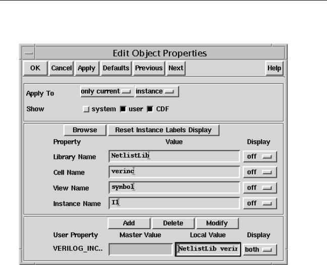
3.Select the placed symbol and open the Edit Object Properties form for it. Add a User
Property called VERILOG_INCLUDE with a value that indicates the full name of the cellview that contains the test code. In Step 1, the code was placed in the cellview
NetlistLib.verinc:verilog_include, so in this step enter the corresponding
April 2004 |
319 |
Product Version 5.3 |
Virtuoso AMS Environment User Guide
Producing Customized Netlists
value NetlistLib verinc verilog_include, leaving out the punctuation. Apply the changes. After these steps, the form looks like this.
4.Create the override file. The override file is associated with only theverinc cell, so the appropriate override file to use is alibInit.il in the NetlistLib library.
;;=======================================================================
;;A custom netlist procedure for macro substitution.
;;=======================================================================
(defun myInstanceVerilogInclude (formatter cellview inst)
(let (lcv file)
;; Check for property VERILOG_INCLUDE on the instance
;;
(when inst->id->VERILOG_INCLUDE
(setq lcv (parseString inst->id->VERILOG_INCLUDE)) ;; Get the the default file name verilog.v
(setq file (ddGetObj (car lcv) (cadr lcv) (caddr lcv) "verilog.v"))
;; Read in the file and print the contents (if (null file)
(progn
sprintf(errmsg "Expected a verilog.v in %s:%s.%s\n" (car lcv) (cadr lcv) (caddr lcv) )
April 2004 |
320 |
Product Version 5.3 |
Virtuoso AMS Environment User Guide
Producing Customized Netlists
(amsError formatter errmsg)
)
(prog (filePort lineBuffer)
;; Open the file, and start printing contents of the file (setq filePort (infile file->readPath))
(while (gets lineBuffer filePort) (amsPrint formatter lineBuffer)
) ; while
(close filePort) ) ; prog
) ; if
) ; when
) ; let
) ; defun
5.Open the Edit Component CDF form for the netlistLib.verinc cell, then from that form open the Edit Simulation Information form. Choose the ams simulator and add the name of the overriding netlisting procedure in the netlistProcedure field. After these steps, the form looks like this:
6.Click OK, in the Edit Component CDF form.
7.Netlist the schematic.
The generated netlist includes the checking code that you specified inStep 1. An excerpt from the netlist looks like this:
nmos #(.ps(1.268u), .as(2.04E-12), .l(130.0n), .pd(12.68u), .ad(2.04E-12),
.w(6u), .m(2))
(* integer library_binding = "analogLib"; integer passed_mfactor = "m"; *)
M1 ( out_y, net20, cds_globals.„nd! , •ulk_n_gnd! );
nmos #(.ps(11.6u/10), .as(1.32E-12/10), .l(130.0n), .pd(9.8u/10), .ad(1.14E- 12/10),
.w(6u/10), .m(2*10))
April 2004 |
321 |
Product Version 5.3 |

Virtuoso AMS Environment User Guide
Producing Customized Netlists
(* integer library_binding = "analogLib"; integer passed_mfactor = "m"; *)
M0 ( net20, net9, cds_globals.„nd! , •ulk_n_gnd! );
//--- begin included file ---
//Design debugger/monitor
parameter TCOff=0;
‘ifdef CHECK_INPUT_TRANSITIONS
always @(posedge(TCOff||in_d) or negedge(TCOff||in_d))
if (eval==1’b1)
$display($stime," WARNING: %m in_d transition (evaluate is active)"); always @(posedge(TCOff||out_y) or negedge(TCOff||out_y))
if (eval==1’b1)
$display($stime," INFO: %m out_y transition (evaluate is active)");
‘endif
// ---- end of included file ----
Example: Using CDF Instance Parameters to Define Inherited Connections
This example illustrates how to establish inherited connections on programmable nodes in such a way that the names and values of the inherited connections are calculated from object properties and can vary for each instance. This allows each of the instances within a single schematic to have different inherited connections.
For example, assume that you have an instance, M1, and that the Substrate connection
field of the Edit Object Properties form for that instance contains the valuesub!. That value needs to result in an inherited connection definition, like this.
wire
(* integer inh_conn_prop_name="\\sub! ";
integer inh_conn_def_value="cds_globals.\\sub! "; *) \sub!_sub! ;
The inherited connection is to be used to instantiate the instance, like this.
ns3v025d #(.as(4.64E-12), .ps(1.664E-05), .m(3), .ad(4.64E-12),
.pd(1.664E-05),.l(3.2E-07), .w(1E-05)) (* integer library_binding = "cmos025";
integer passed_mfactor = "m"; *)
M1 ( D1, G, S, Bulk, Dnw, \sub!_sub! );
These results can be achieved by using a netlisting function to build, from the instance information contained in the Edit Object Properties form, an appropriate list for the extraTerminals field of the Edit Simulation Information form. The netlister then recalculates and uses that list to construct the necessary instantiation statements for each programmable node of each instance.
To implement this technique, use the following steps.
1. Determine what object properties are to be used as input to the netlisting function.
April 2004 |
322 |
Product Version 5.3 |

Virtuoso AMS Environment User Guide
Producing Customized Netlists
The component being netlisted for this example is a mosfet, which has three programmable nodes. By examining the Edit Component CDF form for the cell, you find that the programmable nodes are: bulkNode, sub_node, and dnw_node. These are the names you use in the netlisting function, as described in the next step.
2.Prepare the netlisting function. The function must generate lists that are appropriate for the extraTerminals field of the cell CDF, using as input the object property values associated with each instance. If no object property values are specified, the function needs to create default output.
The following function is one example that meets these requirements.
(defun AMSnmos_dnw_inhExtraTerminals (inst "g")
(let
;; Default values
( (term1 ’(nil name "B" direction "inputOutput" netExpr)) (netExpr1 "[@vbulk_n:%:vssa!]")
(term2 ’(nil name "DNW" direction "inputOutput" netExpr)) (netExpr2 "[@vdnw:%:not_set!]")
(term3 ’(nil name "SUB" direction "inputOutput" netExpr)) (netExpr3 "[@vsub:%:not_set!]")
)
;;Override values, if any. (if (inst != nil) then
(if (inst->bulkNode != "") then
netExpr1 = (strcat "[@" inst->bulkNode ":%:" inst->bulkNode "]")
)
(if (inst->dnw_node != "") then
netExpr2 = (strcat "[@" inst->dnw_node ":%:" inst->dnw_node "]")
)
(if (inst->sub_node != "") then
netExpr3 = (strcat "[@" inst->sub_node ":%:" inst->sub_node "]")
)
)
;;Generate the dynamic "extraTerminals" list.
extraTerminals = (list (append1 term1 netExpr1) (append1 term2 netExpr2)
(append1 term3 netExpr3) )
);let
);defun
For example, the function generates the following default value for B.
(nil name "B" direction "inputOutput" netExpr "[@vbulk_n:%:vssa!]")
Referring to “extraTerminals” on page 590, you see that this value instructs the AMS netlister to create a connection for a terminal B in the instance connection port list for all instances of the mosfet device. The terminal is to be an input/output terminal. The netlist expression indicates that a property called vbulk_n is to be consulted for the name of the net to which terminal B is to be connected. In addition, if vbulk_n is not found, the vssa! net is to be used.
April 2004 |
323 |
Product Version 5.3 |
Virtuoso AMS Environment User Guide
Producing Customized Netlists
The most interesting part of this function, however, is the Override values section.
In that section, the if statements of the form
(if (inst->bulkNode != "") then |
|
netExpr1 = (strcat "[@" inst->bulkNode ":%:" inst->bulkNode "]") |
) |
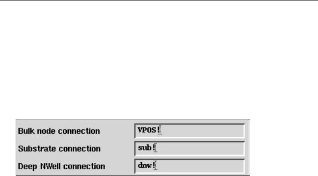
check for a value entered in a field of the Edit Object Properties form and generate a netExpr based on that value. In this function, inst->bulkNode refers to the value entered in the Bulk node connection field. Thednw_node and sub_node terms refer to the Substrate connection and Deep NWell connection fields. Assuming that values like the following have been entered into the fields of the Edit Object Properties form for a particular instance,
the function generates an extraTerminals list like this.
((nil name "B" direction "inputOutput" netExpr "[@VPOS!:%:VPOS!]") (nil name "DNW" direction "inputOutput" netExpr "[@dnw!:%:dnw!]") (nil name "SUB" direction "inputOutput" netExpr "[@sub!:%:sub!]"))
The netlister then uses the extraTerminals list to generate inherited connections in the netlist.
3.Place the function in an override file. The function described in this example is associated with only the mosfet cell, so the appropriate override file to use is alibInit.il in the library that contains the cell.
4.Enter the name of the function in the extraTerminals field of the cell CDF.
a.From the CIW, choose Tools – CDF – Edit.
The Edit Component CDF form appears.
b.Specify the instance master in the Library Name and Cell Name fields.
The form expands to display the information for that master.
c.Ensure that CDF Type is set to Base.
d.Scroll down to the Simulation Information section and click Edit.
The Edit Simulation Information form appears.
e.Ensure that ams appears in the Choose Simulator field.
April 2004 |
324 |
Product Version 5.3 |
Virtuoso AMS Environment User Guide
Producing Customized Netlists
f.Scroll down to the extraTerminals field and enter the name of the function, using the following format.
FUNCTION AMSnmos_dnw_inhExtraTerminals
g.Click OK in the Edit Simulation Information form.
h.Click OK in the Edit Component CDF form.
Now whenever the netlister consults the extraTerminals field, the value of the field is calculated by the function.
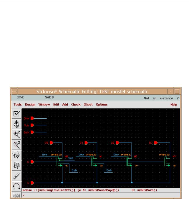
5.Open the schematic that contains the instances that you want to connect with inherited connections.
For example, a schematic containing four instances of a mosfet might look like this.
6.Highlight an instance for which you want to create an instance-specific inherited connection and choose Edit – Properties – Objects from the menu of the schematic editing window.
The Edit Object Properties form appears.
7.Set the values of the programmable nodes for this instance.
April 2004 |
325 |
Product Version 5.3 |

Virtuoso AMS Environment User Guide
Producing Customized Netlists
The programmable nodes for the mosfet symbol appear as the Bulk node connection,
Substrate connection, and Deep NWell connection fields. The illustration inStep 2 shows some possible values. The fields can also be left blank if you want the default net expression for that programmable node of the instance. (The default net expression is defined in the function, as described inStep 2.)
8.Netlist the schematic that contains the instances of interest.
Notice how the inherited connections for the instances are affected by the values you enter in Step 7. For example, if the programmable node fields are left blank for instance
M0 and if the fields are set with the valuesVPOS!, sub!, and dnw! for instance M3, the resulting (partial) netlist looks like this.
module mosfet ( G,Bulk,D3,S,D1,Sub,Dnw,D0,D2 );
input G; input Bulk; input D3; input S; input D1; input Sub; input Dnw; input D0; input D2;
wire
(* integer inh_conn_prop_name="\\sub! ";
integer inh_conn_def_value="cds_globals.\\sub! "; *) \sub!_sub! ;
wire
(* integer inh_conn_prop_name="\\dnw! ";
integer inh_conn_def_value="cds_globals.\\dnw! "; *) †nw!_dnw! ;
wire
(* integer inh_conn_prop_name="\\VPOS! ";
integer inh_conn_def_value="cds_globals.\\VPOS! "; *) \VPOS!_VPOS! ;
wire
(* integer inh_conn_prop_name="\\bulk! ";
integer inh_conn_def_value="cds_globals.\\bulk! "; *) •ulk!_bulk! ;
ns3v025d #(.as(4.64E-12), .ps(1.664E-05), .m(5), .ad(4.64E-12), .pd(1.664E- 05),
.l(3.2E-07), .w(1E-05))
(* integer library_binding = "cmos025"; integer passed_mfactor = "m"; *)
M3 ( D3, G, S, \VPOS!_VPOS! , \dnw!_dnw! , \sub!_sub! );
ns3v025d #(.as(4.64E-12), .ps(1.664E-05), .m(2), .ad(4.64E-12), .l(3.2E-07),
.pd(1.664E-05), .w(1E-05))
(* integer library_binding = "cmos025"; integer passed_mfactor = "m"; *)
M0 ( D0, G, S, Bulk, Dnw, Sub );
...
endmodule
April 2004 |
326 |
Product Version 5.3 |