


Virtuoso AMS Environment User Guide
Working with Schematic Designs
Inherited Connections
The inherited connections solution allows you to selectively override global signals in designs originated in the Virtuoso schematic editor. This solution also allows you to create special global signals and override their names for selected branches of the design hierarchy. The inherited connection capability is not supported for either VHDL (digital) or VHDL-AMS design units.
With the inherited connections feature you can use
■Multiple power supplies in a design
■Overridable substrate connections
■Parameterized power and ground symbols
The inherited connections feature is recognized by all tools throughout the IC design flow. To learn about using inherited connections and net expressions with various Cadence tools in the design flow, refer to theInherited Connections Flow Guide. For more information about using inherited connections in schematics, see the “Inherited Connections” section, of the “Understanding Connectivity and Naming Conventions” chapter in theVirtuoso Schematic Editor User Guide.
This section describes the following information about inherited connections:
■Global Signals in the Schematic Editor on page 167
■Inherited Connections in a Hierarchy on page 168
■Defining Inherited Connections on page 170
■How Net Expressions Evaluate on page 171
Global Signals in the Schematic Editor
A global signal is a signal that is connected by name across all levels of a design hierarchy without using pins. In schematics, a global signal is determined by name; if the signal name ends with an exclamation point ( ! ), it is considered global. A signal that is explicitly passed everywhere in a design is not considered global. A global signal connects to other signals with the same name elsewhere in the hierarchy without requiring an explicit connection through the hierarchy.
April 2004 |
167 |
Product Version 5.3 |
Virtuoso AMS Environment User Guide
Working with Schematic Designs
Inherited Connections in a Hierarchy
You use inherited connections to selectively override global signals within the Verilog (digital) and Verilog-AMS sections of your design. Inherited connections are not supported for either
VHDL (digital) or VHDL-AMS design units. Consider the following example:
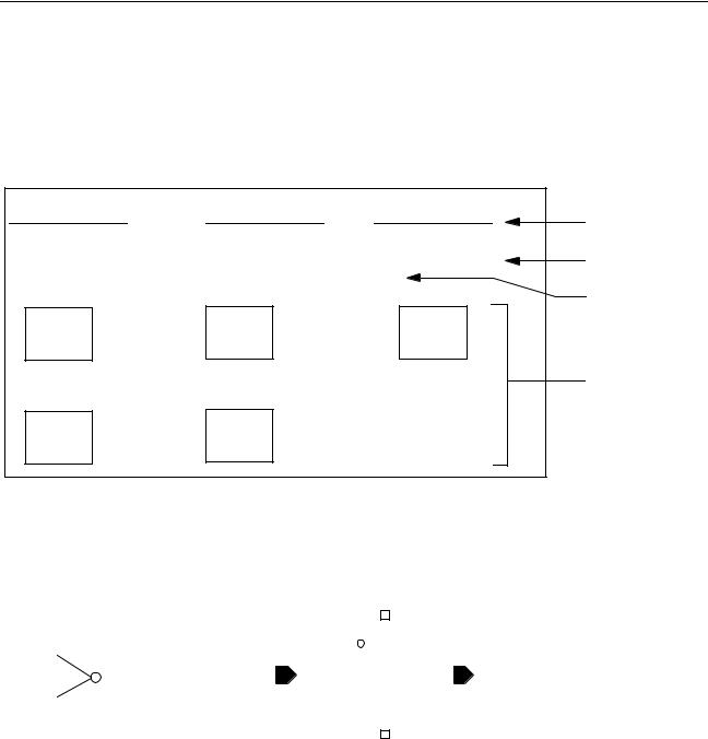
High-Level Schematic
vdd! |
3V! |
analogVdd |
|
power=3V! |
power=analogVdd |
I1 |
I2 |
I3 |
cellA |
cellB |
cellC |
I4 |
I5 |
|
cellA |
cellB |
|
Wire segments and wire names
Property names
Instances
Lower-Level Schematic |
|
|
|
|
|
|
|
|
|
|
|
|
|
|
|
|||||||
Inverter Symbol |
|
Inverter Schematic |
|
|
|
|
|
|||||||||||||||
|
|
|
|
|
|
|
|
|
|
|
|
|
|
|
|
|
|
|
|
|
|
vdd_inherit -> |
|
|
|
|
|
|
|
|
|
|
|
|
|
|
|
|
|
|
|
|
|
|
|
|
|
|
|
|
|
|
|
|
|
p |
|
|
|
vdd_inherit |
||||||||
|
|
|
|
|
|
|
|
|
|
|
|
|
||||||||||
|
|
|
|
[@instanceName] |
|
|
|
|
|
[@power:%:vdd!] |
||||||||||||
|
|
|
|
|
|
|
|
|
|
|
|
|
|
|
|
|
|
|||||
|
A |
|
|
|
|
|
|
|
|
|
|
|
|
|
|
|
Y |
|
||||
|
|
|
|
|
|
Y |
|
A |
|
|
|
|
|
|
|
|
|
|
|
|
||
|
|
|
|
|
|
|
|
|
|
|
|
|
|
|
|
|
|
|
||||
|
|
|
|
|
|
|
|
|
a |
|
|
|
|
|||||||||
|
|
|
|
|
|
|
|
|
|
|
|
|||||||||||
|
|
|
|
inv |
|
|
|
|
|
|
|
|
|
|
|
|
gnd_inherit |
gnd_inherit -> |
||||
|
|
|
|
|
|
|
|
|
|
|
|
|
|
|
|
|||||||
|
|
|
|
|
|
|
|
|
|
|
|
|
|
|
|
|
|
|
|
|||
|
|
|
|
|
|
|
|
|
|
|
|
|
|
|
|
|
|
|
|
|||
|
|
|
|
|
|
|
|
|
|
|
|
|
|
|
|
|
|
|
|
|||
|
|
|
|
|
|
|
|
|
|
|
|
|
|
|
|
|
|
|
|
[@gnd:%:gnd!] |
||
|
|
|
|
|
|
|
|
|
|
|
|
|
|
|
|
|
|
|
|
|||
|
|
|
|
|
|
|
|
|
|
|
|
|
|
|
|
|
|
|
|
|
|
|
|
|
|
|
|
|
|
|
|
|
|
|
|
|
|
|
|
|
|
|
|
|
|
|
|
|
|
|
|
|
|
|
|
|
|
|
|
|
|
|
|
|
|
|
|
|
|
|
|
|
|
|
|
|
|
|
|
|
|
|
|
|
|
|
|
|
|
|
|
The high-level schematic shows five instances:I1, I2, I3, I4, and I5. Each instance represents a portion of the design, each of which eventually references the inverter shown below the high-level schematic.
April 2004 |
168 |
Product Version 5.3 |

Virtuoso AMS Environment User Guide
Working with Schematic Designs
In the inverter schematic, the power and ground wires are defined using the net expressions
[@power:%:vdd!] and [@gnd:%:gnd!], respectively. By default, all inverter pmos transistors are connected to vdd! and all nmos transistors are connected to gnd!.
In the high-level schematic, all the inverter pmos transistors below instance I2 of cellB are to use 3V! as the power supply, and the inverters in instance I3 of cellC are to use analogVdd.
To selectively override the default global signal vdd!, you create a netSet type property on instance I2 named power with the value 3V! and a netSet type property on instance I3 named power with the value analogVdd. Notice that the inverters below instances I1, I4, and I5 are still connected to vdd!.
In other words, you place a netSet property on an instance representing the branch of hierarchy where it is to be applied. You can create the netSet property on any instances at any level above the cellviews with net expressions. For example, if a large hierarchical design has seven levels of hierarchy, you can place a netSet property power = 3V! on an I2 instance in the top-level schematic. This affects all the logic below instance I2 all the way to the bottom in all cellviews that contain a net expression, such as [@power:%:vdd!]. All cellviews that contain this net expression use 3V! instead of vdd! for that branch of the design.
However, if on a lower-level cellview there is an I7 instance with a netSet property power = 2V!, then 2V! is always used below the I7 instance.
April 2004 |
169 |
Product Version 5.3 |
Virtuoso AMS Environment User Guide
Working with Schematic Designs
Defining Inherited Connections
In the schematic editor, you define an inherited connection by adding a net expression label to either a wire or a pin. A net expression defines the default global signal name for the connection and the name of a property that can be used to override that default global signal name.
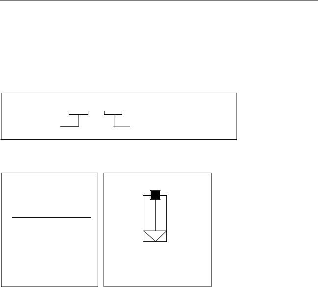
Example Net Expression
|
[@power:%:vdd!]* |
Property name |
Default global signal name |
Example Net Expression Labels
[@vdd:%:vdd!]*
Schematic wire with a net expression label
[@gnd:%:gnd!]*
Ground supply symbol containing a symbol pin with a net expression label
The asterisk ( * ) after a global name shows that this is not a regular wire name but a name that is an overridable net expression.The default global signal name specifies what the wire or pin is connected to by default.
You can create an inherited connection in a schematic by placing an instance of a symbol where one of the symbol pins has a net expression label. When you run the checker program
April 2004 |
170 |
Product Version 5.3 |