


Virtuoso AMS Environment User Guide
Working with Schematic Designs
input inSig; input trigger; output holdSig;
electrical gnd, inSig, holdSig; real value;
analog begin
// A digital event to which analog is made sensitive @(posedge(trigger))
value = V(inSig);
V(holdSig) <+ transition( value, 1n, 2.5n);
end
endmodule
When you save the module and quit the text editor window, the AMS environment checks the syntax in the text file. If the syntax checker finds any errors or problems, a dialog box appears with a message like the following:
Parsing of verilog-ams file failed:
Do you want to view the error file and re-edit HDL?
Click Yes to display the HDL Parser Error/Warnings window and to reopen the module file for editing.
Editing Verilog-AMS and VHDL-AMS Cellviews Outside of the AMS Environment
You can create Verilog (digital), Verilog-AMS, VHDL (digital) and VHDL-AMS source files either inside or outside of the AMS environment. However, if you use source files created outside of the AMS environment you give up the automatic cross-checking among views that the environment performs. For example, if, outside the environment, you edit the port list of a text view, you must remember to update the corresponding symbol view. If you make a similar change within the environment, AMS Designer automatically prompts you to update the symbol.
If you do create HDL views outside of the environment, ensure that they are compiled by choosing the AMS Design Prep compile all option. For example, from the Command
Interpreter Window (CIW) choose AMS – Design Prep to open the AMS Design Prep form.
In that form, select Compile and All, and then click Run.
Descend Edit
To examine the views below the symbols while viewing a schematic, choose Design –
Hierarchy – Descend Edit. For example, there might be three view choices: symbol,
April 2004 |
160 |
Product Version 5.3 |
Virtuoso AMS Environment User Guide
Working with Schematic Designs
verilogAMS, and daconv_behav. If you choose verilogAMS, a text window appears, as shown in the following figure.
Creating a Verilog-AMS Cellview
To create a new component with only a Verilog-AMS cellview,
1. From the CIW, choose File – New – Cellview.
April 2004 |
161 |
Product Version 5.3 |
Virtuoso AMS Environment User Guide
Working with Schematic Designs
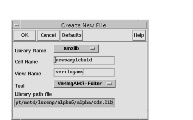
The Create New File form appears.
2.Specify the Cell Name (component).
3.Set the Tool cyclic field toVerilogAMS-Editor.
4.In the View Name field, type the name for the new cellview. To comply with AMS guidelines, the name should be all lower-case.
5.Click OK.
April 2004 |
162 |
Product Version 5.3 |
Virtuoso AMS Environment User Guide
Working with Schematic Designs
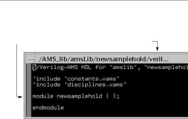
A text editor window appears for the new module. If the cell name you typed in the Cell
Name field is new, an empty template appears. If the name you typed already has available views, a template appears with pin and parameter information in place.
The module must have the same name as the cell.
The UNIX file directory has the same name as the view name.
6.Modify any existing pin or parameter information as necessary. You can add unique or shared parameters as required by your design.
7.Complete the module. Be sure that the module name remains the same as the name of the cell.
8.Save the module, and quit the text editor window.
Creating a VHDL-AMS Cellview
To create a new component with only a VHDL-AMS cellview,
1. From the CIW, choose File – New – Cellview.
April 2004 |
163 |
Product Version 5.3 |
Virtuoso AMS Environment User Guide
Working with Schematic Designs
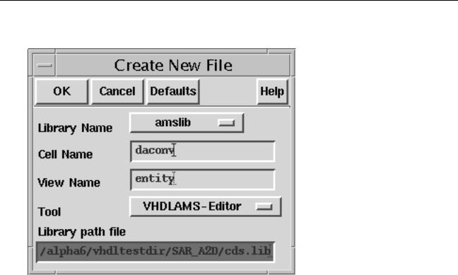
The Create New File form appears.
2.Specify the Cell Name (component).
3.Set the Tool cyclic field toVHDLAMS-Editor.
4.In the View Name field, type the name for the new cellview. To comply with AMS guidelines, the name should be all lower-case. If the view name you enter is entity, the created view is a VHDL-AMS entity. If the view name you enter is anything other than entity, the created view is an architecture.
5.Click OK.
A text editor window appears for the new module. If the cell name you typed in the Cell Name field is new, an empty template appears. If the name you typed already has
April 2004 |
164 |
Product Version 5.3 |

Virtuoso AMS Environment User Guide
Working with Schematic Designs
available views and you are creating an entity view, a template appears with pin and parameter information in place.
The entity has the same name as the cell.
The UNIX file directory has the same name as the view name.
6.Modify any existing pin or parameter information as necessary. You can add unique or shared parameters as required by your design.
7.Complete the module. Be sure that the architecture or entity name remains the same as the name of the cell.
8.Save the module, and quit the text editor window.
Creating a Symbol Cellview from a Verilog-AMS Cellview
If you created a Verilog-AMS cellview without creating a symbol, or if you have a component with only a Verilog-AMS cellview, you can add a symbol view by following these steps:
1.Choose File – Open from the CIW. The Open File form appears.
2.Open any schematic or symbol cellview.
April 2004 |
165 |
Product Version 5.3 |
Virtuoso AMS Environment User Guide
Working with Schematic Designs
The editor appears.
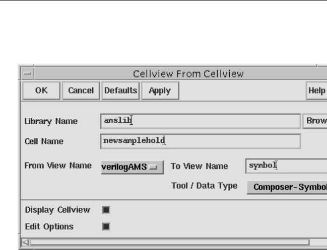
3.Choose Design – Create Cellview – From Cellview.
The Cellview From Cellview form appears.
4.Fill in the Library Name and Cell Name fields.
If you do not know this information, click Browse, which opens the Library Browser, so you can browse available libraries and components.
5.In the From View Name cyclic field, select the Verilog-AMS view.
6.In the Tool / Data Type cyclic field, chooseComposer-Symbol.
7.In the To View Name field, typesymbol.
8.Click OK.
The Symbol Generation Options form appears.
9.Click OK.
A Symbol Editor window appears.
10.Edit the symbol, save it, and close the Symbol Editor window.
April 2004 |
166 |
Product Version 5.3 |