


Virtuoso AMS Environment User Guide
Using Test Fixtures
■To create the fixture outside of the AMS environment,
a.Use a text editor to create the module. When you are finished, save the file that contains the module.
b.Compile the module, being sure to use the -use5x option. This option creates a new cell and view for the test fixture in the working library.
Because the test fixture module is the highest simulation level, the module has no ports. The other content of the test fixture module depends on the inputs and outputs that you need to provide and examine. A typical Verilog-AMS structure looks like this:
module test_fixture_name () ; |
// There are no ports. |
signal_declarations_for_stimuli |
|
instantiation_of_top_level_module instantiations_of_behavioral_testbench_modules_or_primitives digital_behavioral_constructs_like_initial_and_always_blocks analog_blocks_to_generate_analog_stimuli
endmodule
Test fixtures can be simple, perhaps providing only a stimulus, or they can be very complex, testing complete cycles of the top-level module. Test fixtures like the latter might provide stimuli to the inputs, read the outputs, and then react by providing new stimuli that depend on the outputs.
Using a Test Fixture
To use the test fixture, you specify it as the highest level in a configuration, with the top-level module (the one being tested) at the next level below. The view to use for a Verilog-AMS test fixture is the Verilog-AMS view. For information on creating a configuration, se“Creatinge a Config Cellview” on page 200.
Example: Creating and Using a Test Fixture
This simple example uses only two modules, both of them Verilog-AMS text modules. The first,testfixture, instantiates the other module myswitch. The myswitch module describes a basic on/off switch controlled by a digital control signal. When the control signal is high, the switch passes the current from its input port to its output port. The goal of the example is to verify the operation of the myswitch module by instantiating the switch in the test fixture and then running a simulation.
First create the modules and bring them into the library.
1.Assume that the myswitch module exists in the fileswitchcomps.vams. The module
(which is only one of the modules in the file) looks like this.
April 2004 |
195 |
Product Version 5.3 |

Virtuoso AMS Environment User Guide
Using Test Fixtures
//Verilog-AMS HDL for "amslib", "myswitch" "verilogams"
‘include "constants.vams" ‘include "disciplines.vams"
module myswitch (analogin, analogout, logicsignal ); input analogin, logicsignal ;
output analogout ;
electrical analogin, analogout ;
analog
begin
if (logicsignal == 1) V(analogout) <+ V(analogin) ; else I(analogin, analogout) <+ 0.0 ;
end endmodule
2.Compile the module into the verilogams view, of the myswitch cell, of the amslib library. The shorthand way of referring to this view is amslib.myswitch:verilogams. The appropriate command is:
ncvlog -ams -use5x -specificunit amslib.myswitch:verilogams switchcomps.vams
3.Create the test fixture in the AMS environment so it is located in theamslib library too. This module provides the inputs for the instantiated myswitch module and then reads the outputs to ensure that the module operates as it should.
a.Select File – New – Cellview from the menu in the CIW.
b.In the Create New File dialog box, choose VerilogAMS-Editor in the Tool field.
c.Choose the amslib library to hold the test fixture.
d.Type in the cell name testfixture and the view name verilogams. Remember that the cell name must be the same as the module name that you plan to use.
e.Click OK.
f.In the editor window that appears, type in the code for the module. Save it when you are done.
The code to use for the module is
module testfixture ( ); electrical ain, aout ; reg logsig ;
ground gnd ; electrical gnd ;
myswitch mys(ain, aout, logsig) ; // Instantiate the component
resistor #(.r(1000)) r1 (aout, gnd) ;
analog begin
V(ain) <+ 0.5 ; // Generate the analog stimuli. @(cross(V(aout)-0.25, +1))$strobe ("Turns on") ; // Read the output. @(cross(V(aout)-0.25, -1))$strobe ("Turns off") ;
end
April 2004 |
196 |
Product Version 5.3 |

Virtuoso AMS Environment User Guide
Using Test Fixtures
initial begin logsig = ’b1 ;
$strobe ("Switch on") ; end
always begin
#200 logsig = ~logsig ; // Generate the digital stimuli. #200 if (logsig == 1) $strobe ("Switch on") ;
else $strobe ("Switch off");
end
endmodule
At this point both modules parse successfully and exist in the library. The next steps match the steps used to run any simulation in the AMS environment.
1. Create a config for the test fixture.
April 2004 |
197 |
Product Version 5.3 |
Virtuoso AMS Environment User Guide
Using Test Fixtures
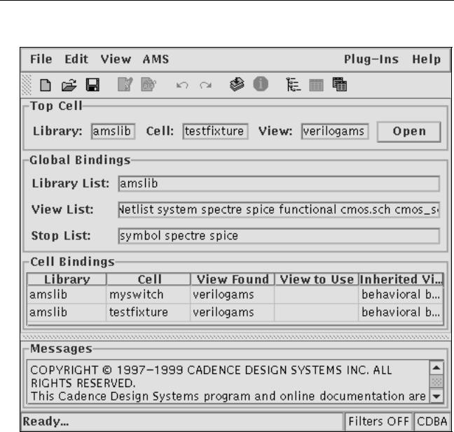
Displayed in the hierarchy editor, it might look like this:
2.Use the selections in the AMS menu to prepare the design and simulate.
You can use SimVision to examine waveforms and use the information printed by the test
fixture to determine whether your instantiated component works as desired.
April 2004 |
198 |
Product Version 5.3 |