


Virtuoso AMS Environment User Guide
Preparing a Design for Simulation
2.When you are finished editing the list of global signals, clickOK for your edits to take effect.
Unaliasing Global Signals
To unalias signals
1.Select the signals to be unaliased from the group, and then click Unalias.
2.When you are finished editing the list of global signals, clickOK for your edits to take effect.
Specifying Design Variables
Design variables can be used in master CDBA or master HDL data but AMS Design Prep is aware of only the former. AMS Design Prep is aware of design variables that are copied to CDBA cellviews by the Cadence analog design environment. If a design variable is set in multiple locations in a hierarchy, the effective CDBA value is the one set at the highest level of the hierarchy. That value, in turn, can be overridden by specifying a value in the AMS
Design Variables form.
AMS Designer implements design variables as out-of-module references, but does not support out-of-module references either into or out of VHDL-AMS design units. As a result, AMS Designer does not support direct access of design variables in or from within
VHDL-AMS design units, even if you enter the VHDL-AMS design variables in the AMS Design Variables window.
In addition, AMS Design Prep assumes that variables are design variables when
■The variables are used in the values of properties or parameters, and
■The variables are not themselves defined as cellview properties or parameters.
For example, a parameter phase has the value sin(x)*3 where the variable x is not defined as a parameter. AMS Design Prep assumes that the variable x is a design parameter and generates a netlist with the statement .phase(sin(cds_globals.x)*3).
You can use the AMS Design Variables window to add a new design variable or to remove a design variable that is in the master HDL data. You can also set the values of design variables found in master CDBA data and revert back to the original CDBA values when necessary.
When you make changes in the AMS Design Variables window and click OK, AMS Design
Prep
■Creates and compiles the cds_globals module if it does not already exist.
April 2004 |
216 |
Product Version 5.3 |
Virtuoso AMS Environment User Guide
Preparing a Design for Simulation
■Regenerates and recompiles the cds_globals module if it does already exist.
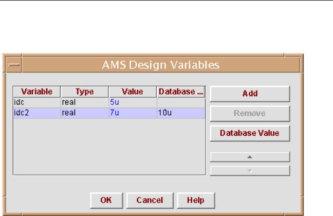
To display the AMS Design Variables window, choose AMS – Design Variables.
The display color of the values in the table indicates whether AMS Design Prep found the design variable or you added it. If you added the design variable, the value displays in blue. If AMS Design Prep found the design variable, the value displays in black.
The black color means that you cannot remove that variable. You cannot remove a design variable found by AMS Design Prep or add a design variable with the same name as a design variable found by AMS Design Prep because doing so results in an undefined reference when you elaborate the design. However, if you added a design variable in a previous design session, and it has the same name as a design variable found by AMS Design Prep during the current design session, then the design variable that you added in the previous session is used, and its value displays in black, so you cannot remove the design variable. This behavior is useful when you change the configuration data while switching back and forth between behavioral and schematic views. If AMS Design Prep cannot find a design variable in the CDBA data in the current run, but found it in a previous run, the value of the variable displays in red. You can remove a variable that displays a red value because the variable is not used in the current configuration.
If the controls are disabled, AMS Design Prep might be unable to write to the cds_globals module where the information in the window is stored. For more information, see “How AMS Design Prep Handles Global Signals and Design Variables” on page 225.
April 2004 |
217 |
Product Version 5.3 |

Virtuoso AMS Environment User Guide
Preparing a Design for Simulation
Adding a Design Variable
To add a design variable,
1.Click Add.
A new row, representing a new design variable, appears in the table.
2.(Optional) Click in the Variable field of the new variable and change the default name to the name you want to use.
3.Choose real or integer for the Type field.
4.Type the value of the variable in the Value field.
The value you enter can have a scaling factor but must not have a measurement unit.
Measurement units are not supported by the Verilog-AMS language.
5.If necessary, highlight a row and click the up or down arrows to rearrange the order of the variables.
You might need to do this if you have a design variable whose value depends on the value of another parameter. For example, if you have a parameter idc with the value
5 * myparam, you must ensure that myparam is defined earlier (higher) in the list of design variables.
6.When you finish adding design variables, clickOK.
Deleting a Design Variable
To remove a design variable, click the name of the variable to highlight it, then click
Remove.
Editing the Value of a Design Variable
You can edit the value of any design variable. The design variable values are saved verbatim in the cds_globals module, and are used during simulation. To edit a design variable,
1.Set the new type and value in the Type and Value fields of the variable that you want to change. Note, however, that although you can change the value of a variable found in the CDBA data, you cannot change the type.
The value you enter can have a scaling factor but must not have a measurement unit.
2.When you finish editing design variables, clickOK.
April 2004 |
218 |
Product Version 5.3 |
Virtuoso AMS Environment User Guide
Preparing a Design for Simulation
Reverting to the Value Used in the CDBA
To revert the value of a design variable found in the CDBA to the value used in the CDBA,
1.Click the name of the design variable in the Variable column.
2.Click Database Value.
The Database Value button is active only when the highlighted variable is found in the CDBA and has a value there.
3.When you finish editing the list of design variables, clickOK.
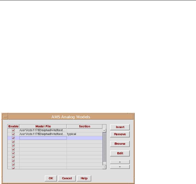
Specifying Model Files to Use During Elaboration
For elaboration, you can specify model files and sections in the AMS Analog Models window. To display the Analog Models window, choose AMS – Analog Models in the Cadence Hierarchy Editor window.
Adding an Analog Model File
To add an analog model file to the table,
1.Do either of the following:
Click on the Model File field of an empty row.
Highlight a row and then click Insert.
A new row appears in the table above the highlighted row.
April 2004 |
219 |
Product Version 5.3 |

Virtuoso AMS Environment User Guide
Preparing a Design for Simulation
2.Type the path and name of the analog model file in theModel File field. You can do either of the following:
Type the information in the fields.
If you like, you can use environment variables to specify the path. For example, you might type the following into the Model File field.
$HOME/test/pwr_supply/models/models.scs
Click Browse to open a dialog that allows you to navigate through your directories to identify the appropriate model file.
When you click away from the row, AMS Designer checks for the existence of the file that you specify and highlights the row in red if the file is not found.
3.(Optional) Type the section that you want to use into the Section field.
Note: AMS Designer does not check for the existence of the section, so be sure that you enter a correct section name.
To specify multiple sections from a single model file, use multiple rows in the table, each with the same model file but with a different section.
You can enable multiple sections only if every model included in those sections is unique. For example, you cannot specify and enable both the section typical and the section slow in the following analog model file because themymos model is included in both.
library mos
section typical
model mymos type=n uo=600 endsection typical
section slow
model mymos type=n uo=400 endsection slow
4.If necessary, highlight a row in the table and click the up or down arrows to rearrange the order of the model files.
Files higher in the list are handled by the elaborator before files lower in the list.
5.When you finish adding analog model files, clickOK.
Deleting an Analog Model File
To remove an analog model file, highlight the row, then clickRemove.
If you want to remove multiple entries, you can use the Shift and Control keys to highlight multiple entries before you click Remove.
April 2004 |
220 |
Product Version 5.3 |