- •Contents
- •Preface
- •Related Documents
- •Typographic and Syntax Conventions
- •Creating HDL Modules for CDBA Cellviews
- •Creating HDL Data as You Save CDBA Cellviews
- •Creating HDL Data from Pre-existing CDBA Cellviews
- •Quick-Start Tutorial
- •The Circuit
- •AMS Designer Tools
- •Setting Up the Tutorial
- •Running from a Script
- •Running within the AMS Environment
- •Opening the Command Interpreter Window
- •Netlisting and Compiling
- •Elaborating and Simulating the Design
- •Summary
- •Setting Up the AMS Environment
- •Overview
- •The hdl.var File
- •The ams.env Files
- •AMS Designer Supports Design Management
- •Specifying the Text Editor to Use
- •Specifying Fonts for the Cadence Hierarchy Editor
- •Preparing to Use AMS Designer from the Hierarchy Editor
- •Netlisting
- •Netlisting Modes Supported by the AMS Netlister
- •Automatic Netlisting of a Cellview
- •Netlist Updating and Netlisting of Entire Designs
- •Netlisting from the UNIX Command Line
- •Library Netlisting
- •Netlisting of Cells in Response to Changes in CDF
- •Preparing Existing Analog Primitive Libraries for Netlisting
- •Specifying the Behavior of the Netlister and Compilers
- •Opening the AMS Options Windows
- •Setting Netlister Options from the Hierarchy Editor
- •Opening the CIW AMS Options Window
- •Setting Compiler Options
- •Viewing the AMS Netlister Log
- •Understanding the Output from the AMS Netlister
- •How Inherited Connections Are Netlisted
- •Inherited Signal Connections
- •Inherited Terminal Connections
- •Instance Values for Inherited Connections
- •Third-Party Tools and Other Cadence Tools
- •How Aliased Signals Are Netlisted
- •How m-factors (Multiplicity Factors) Are Netlisted
- •How Iterated Instances Are Netlisted
- •Passing Model Names as Parameters
- •Effect of the modelname, model, and modelName Parameters
- •Handling of the model* and componentName Parameters
- •Precedence of the model* and componentName Parameters
- •Specifying Parameters to be Excluded from Netlisting
- •Ignoring Parameters for Entire Libraries
- •Example: Specifying Parameters to Ignore
- •Ensuring that Floating Point Parameters Netlist Correctly
- •Working with Schematic Designs
- •Setting Schematic Rules Checker Options for AMS Designer
- •Creating Cellviews Using the AMS Environment
- •Preparing a Library
- •Creating the Symbol View
- •Using Blocks
- •Descend Edit
- •Inherited Connections
- •Global Signals in the Schematic Editor
- •Inherited Connections in a Hierarchy
- •How Net Expressions Evaluate
- •Net and Pin Properties
- •groundSensitivity and supplySensitivity Properties
- •Making Connect Modules Sensitive to Inherited Connection Values
- •Using External Text Designs
- •Overview of Steps for Using External Text Designs
- •Bringing Modules into a Cadence Library
- •Specifying the Working Library
- •Compiling into Libraries
- •Compiling into Temporary Libraries
- •Listing Compiled Modules
- •Using Text Blocks in Schematics
- •Using Modules Located in a Cadence Library
- •Preparing for Simulation
- •Using Analog Primitives
- •Using SPICE and Spectre Netlists and Subcircuits
- •Preparing to Use SPICE and Spectre Netlists and Subcircuits
- •Placing SPICE and Spectre Netlists and Subcircuits in a Schematic
- •Using Test Fixtures
- •Creating and Using a Textual Test Fixture
- •Creating a Textual Test Fixture
- •Using a Test Fixture
- •Example: Creating and Using a Test Fixture
- •Using Design Configurations
- •Ensuring HDL Design Unit Information Is Current
- •Preparing a Design for Simulation
- •Overview of AMS Design Prep
- •What AMS Design Prep Does to Prepare a Design for Simulation
- •When to Use AMS Design Prep
- •Specifying the Behavior of AMS Design Prep
- •Setting Options for Global Design Data
- •Specifying Global Signals
- •Specifying Design Variables
- •Specifying Model Files to Use During Elaboration
- •Running AMS Design Prep
- •The cds_globals Module
- •Global Signals
- •Design Variables
- •Setting Elaborator Options
- •Setting Simulator Options
- •Setting Waveform Selection Options
- •Creating Probes
- •Selecting Instances from the Virtuoso Schematic Editing Window
- •Selecting Buses
- •Selecting Instances from the Scope Navigator
- •Copying and Pasting Within Tables
- •Elaborating and Simulating
- •Viewing Messages
- •Plotting Waveforms After Simulation Ends
- •Starting the SimVision Waveform Viewer
- •Plotting Waveforms Selected on a Schematic (Direct Plot)
- •Using the amsdesigner Command
- •Examples
- •Producing Customized Netlists
- •Identifying the Sections of a Netlist
- •Using ams.env Variables to Customize Netlists
- •Using Netlisting Procedures to Customize Netlists
- •Examples: Problems Addressed by Customized Netlists
- •Example: Adjusting Parameter Values to Account for Number of Fingers
- •Example: Using Symbols that Represent Verilog Test Code
- •Data Objects Supported for Netlisting
- •Netlister Object
- •Formatter Object
- •Cellview Object
- •Parameter Object
- •Instance Object
- •SKILL Functions Supported for Netlisting
- •Default Netlisting Procedures
- •Netlisting Helper Functions
- •Variables for ams.env Files
- •How AMS Designer Determines the Set of Variables
- •Why AMS Designer Uses ams.env Files, Not .cdsenv Files
- •List of ams.env Variables
- •Detailed Descriptions of ams.env Variables
- •aliasInstFormat
- •allowDeviantBuses
- •allowNameCollisions
- •allowSparseBuses
- •allowUndefParams
- •amsCompMode
- •amsDefinitionViews
- •amsEligibleViewTypes
- •amsExcludeParams
- •amsExpScalingFactor
- •amsLSB_MSB
- •amsMaxErrors
- •amsScalarInstances
- •amsVerbose
- •analogControlFile
- •bindCdsAliasLib
- •bindCdsAliasView
- •cdsGlobalsLib
- •cdsGlobalsView
- •checkAndNetlist
- •checkOnly
- •checktasks
- •compileAsAMS
- •compileExcludeLibs
- •compileMode
- •connectRulesCell
- •connectRulesCell2
- •connectRulesLib
- •connectRulesView
- •detailedDisciplineRes
- •discipline
- •excludeViewNames
- •hdlVarFile
- •headerText
- •ieee1364
- •ifdefLanguageExtensions
- •incdir
- •includeFiles
- •includeInstCdfParams
- •initFile
- •instClashFormat
- •iterInstExpFormat
- •language
- •lexpragma
- •logFileAction
- •logFileName
- •macro
- •maxErrors
- •messages
- •modifyParamScope
- •ncelabAccess
- •ncelabAnnoSimtime
- •ncelabArguments
- •ncelabCoverage
- •ncelabDelayMode
- •ncelabDelayType through ncelabMessages
- •ncelabMixEsc
- •ncelabModelFilePaths
- •ncelabNeverwarn through ncelabVipdelay
- •ncsimArguments
- •ncsimEpulseNoMsg through ncsimExtassertmsg
- •ncsimGUI
- •ncsimLoadvpi through ncsimStatus
- •ncsimTcl
- •ncsimUnbuffered through ncsimUseAddArgs
- •ncvhdlArguments
- •ncvlogArguments
- •ncvlogUseAddArgs
- •netClashFormat
- •netlistAfterCdfChange
- •netlistMode
- •netlistUDFAsMacro
- •neverwarn
- •noline
- •nomempack
- •nopragmawarn
- •nostdout
- •nowarn
- •paramDefVals
- •paramGlobalDefVal
- •pragma
- •processViewNames
- •prohibitCompile
- •runNcelab
- •runNcsim
- •scaddlglblopts
- •scaddltranopts
- •scale
- •scalem
- •scannotate
- •scapprox
- •scaudit
- •sccheckstmt
- •sccmin
- •sccompatible
- •scdebug
- •scdiagnose
- •scdigits
- •scerror
- •scerrpreset
- •scfastbreak
- •scgmin
- •scgmincheck
- •schomotopy
- •sciabstol
- •scic
- •scicstmt
- •scignshorts
- •scinfo
- •scinventory
- •sclimit
- •sclteratio
- •scmacromod
- •scmaxiters
- •scmaxnotes
- •scmaxrsd
- •scmaxstep
- •scmaxwarn
- •scmethod
- •scmodelevaltype
- •scmosvres
- •scnarrate
- •scnotation
- •scnote
- •scopptcheck
- •scpivabs
- •scpivotdc
- •scpivrel
- •scquantities
- •screadic
- •screadns
- •screlref
- •screltol
- •scrforce
- •scscale
- •scscalem
- •scscftimestamp
- •scscfusefileflag
- •scskipcount
- •scskipdc
- •scskipstart
- •scskipstop
- •scspeed
- •scstats
- •scstep
- •scstop
- •scstrobedelay
- •scstrobeperiod
- •sctemp
- •sctempeffects
- •sctitle
- •sctnom
- •sctopcheck
- •sctransave
- •scusemodeleval
- •scvabstol
- •scwarn
- •scwrite
- •simRunDirLoc
- •simVisScriptFile
- •status
- •templateFile
- •templateScript
- •timescale
- •update
- •use5xForVHDL
- •useDefparam
- •useNcelabNowarn
- •useNcelabSdfCmdFile
- •useNcsimNowarn
- •useNowarn
- •useScaddlglblopts
- •useScaddltranopts
- •useScic
- •useScreadic
- •useScreadns
- •useScwrite
- •useSimVisScriptFile
- •useProcessViewNamesOnly
- •verboseUpdate
- •vlogGroundSigs
- •vloglinedebug
- •vlogSupply0Sigs
- •vlogSupply1Sigs
- •wfDefaultDatabase
- •wfDefInstCSaveAll
- •wfDefInstCSaveLvl
- •wfDefInstSaveCurrents
- •wfDefInstSaveVoltages
- •wfDefInstVSaveAll
- •wfDefInstVSaveLvl
- •wfDefInstVSaveObjects
- •Updating Legacy SimInfo for Analog Primitives
- •The ams Fields
- •Special Handling of model, modelName, modelname, and componentName
- •Converting an Existing Analog Primitive Library
- •Designing for Virtuoso AMS Compliance
- •Terminals
- •Buses
- •Component Description Format
- •Parameters
- •Using Inherited Parameters
- •Using Cell Parameters
- •Parameterized Cells
- •VHDL-AMS Component Declarations
- •Properties
- •Properties to Avoid Completely
- •Avoid the portOrder Property Unless Required by Special Circumstances
- •Properties to Use Only in AMS Compatibility Mode
- •Properties That Have No Special Meaning in the AMS Environment
- •Properties Fully Supported by the AMS Environment
- •SKILL Functions
- •amsCheckCV
- •amsIsPresent
- •amsNetlist
- •amsProcessCellViews
- •amsUIOptionsForm
- •amsUIRunNetlisterForm
- •ddsCvtAMSTranslateCell
- •ddsCvtAMSTranslateLib
- •ddsCvtToolBoxAMS
- •vmsUpdateCellViews
- •Customization Variables
- •schHdlNotCreateDB
- •schHdlUseVamsForVerilog
- •vmsAnalysisType
- •vmsCreateMissingMasters
- •vmsNcvlogExecutable
- •vmsPortProcessing
- •vmsRunningInUI
- •vmsTemplateScript
- •vmsVerboseMsgLevel
- •Compiling Cadence-Provided Libraries
- •Purpose of the amsLibCompile Tool
- •Running the amsLibCompile Tool Manually
- •Example
Virtuoso AMS Environment User Guide
Using Existing Designs in the AMS Environment
Using Analog Primitives
Analog primitives must be converted for use in AMS Designer. To do the conversion, you use the Conversion Tool Box, which is opened by choosing Tools – Conversion Tool Box from the CIW and then clicking AMS simInfo from Spectre. The tool box operates on an entire library at a time so the library must contain only analog primitives. For more information about using the Conversion Tool Box, see “Converting an Existing Analog Primitive Library” on page 598
This tool box assumes that the primitives to be converted are already prepared for use with
Spectre Direct. If this is not true, you can
■Use another conversion tool to prepare the primitives for use with Spectre Direct and then do the conversion for AMS. For details about preparing primitives for use with Spectre Direct, see the “Preparing Files for Direct Simulation” section, in the “Converting Design Libraries and Technology Data” chapter of the Compatibility Guide.
■Manually create AMS simulation information for the primitives according to the definitions in Appendix B, “Updating Legacy SimInfo for Analog Primitives,” then use the steps in “PlacingSPICE and Spectre Netlists and Subcircuits in a Schematic” on page 189 to edit the CDF simulation information.
Using SPICE and Spectre Netlists and Subcircuits
This section describes briefly what you must do to use subcircuits, models, and netlists written in SPICE or Spectre. For additional information, see the “Using Subcircuits and Models Written in SPICE or Spectre” section, in the “Instantiating Analog Primitives and Subcircuits” chapter of the Virtuoso AMS Simulator User Guide.
Preparing to Use SPICE and Spectre Netlists and Subcircuits
To prepare to use a subcircuit or a model written in SPICE or Spectre, you must
1.Include the netlist or subcircuit in a model file.
The contents of the model file must be in Spectre or SPICE syntax. Spectre files should start with simulator lang=spectre and SPICE files should start withsimulator lang=spice and end with simulator lang=spectre. This practice protects against an inadvertent language change.
2.Give the elaborator the location of the model file.
April 2004 |
188 |
Product Version 5.3 |
Virtuoso AMS Environment User Guide
Using Existing Designs in the AMS Environment
You can meet this requirement either manually or by using the windows provided by the
AMS environment.
You can give the location manually by defining theMODELPATH variable in the hdl.var file, or by using the-modelpath option for ncelab. For example, an entry in the hdl.var file might look like this:
define MODELPATH model_filename
You can use the Analog Model Files form. For more information, see “Specifying Model Files to Use During Elaboration” on page 219.
Placing SPICE and Spectre Netlists and Subcircuits in a Schematic
After preparing as described in the previous section, you can add a SPICE or Spectre netlist or subcircuit to a schematic. To do so, you
1.Create a symbol for the netlist or subcircuit.
You can use the Library Manager to copy an existing symbol, then modify the new symbol as necessary.
2.Add the CDF termOrder field simulation information for the symbol.
a.From the CIW, choose Tools – CDF – Edit. The Edit Component CDF form opens.
b.In the Edit Component CDF form, select Base for the CDF Type.
c.Type in the names of the library and cell that hold the newly created symbol view.
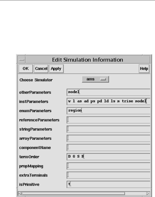
d.Scroll down to the Simulation Information section and click Edit. The Edit Simulation Information form appears.
e.For the Choose Simulator field, selectams.
f.Type the terminal names into the termOrder field.
Neglecting this step causes compilation errors such as
In AMS, named port association for analog primitives is not supported.
3.If your SPICE or Spectre netlist or subcircuit supports models (as, for example, the bjt and resistor do),
April 2004 |
189 |
Product Version 5.3 |
Virtuoso AMS Environment User Guide
Using Existing Designs in the AMS Environment
a.Type model into the instParameters and otherParameters fields.
This tells the netlister that there is a model associated with the symbol.
b.Type a t into the isPrimitive field.
This tells the netlister to translate the cell to a Spectre primitive that supports models.
At the end of this series of steps, the Edit Simulation Information form might look like this.
April 2004 |
190 |
Product Version 5.3 |
Virtuoso AMS Environment User Guide
Using Existing Designs in the AMS Environment
4.If you are placing a Spectre built-in primitive that does not support models (such as vdc or vsin), type the name of the primitive into the componentName field.
5.Click OK to close the Edit Simulation Information form.
6.In the Edit Component CDF form, click Add to open the Add CDF Parameter form.
Type in any required parameters. When you close the form, the added parameters appear in the Component Parameters pane of the Edit Component CDF form.
7.Close the Edit Component CDF form, by clicking OK.
8.Place the symbol in your schematic.
For more information about this step, see the “Creating Schematics” chapter of the
Virtuoso Schematic Editor User Guide.
April 2004 |
191 |
Product Version 5.3 |
Virtuoso AMS Environment User Guide
Using Existing Designs in the AMS Environment
April 2004 |
192 |
Product Version 5.3 |