

Accellera |
|
Version 2.3.1, June 1, 2009 |
VERILOG-AMS |
Here each parameter is listed with the new value to be used for that parameter.
7.7.4 connect_mode
This can be used to specify additional segregation of connect modules at each level of the hierarchy. Setting connect_mode to split or merged defines whether all ports of a common discrete discipline and port direction share an connect module or have individual connect modules.
Example:
connect a2d_035u split #(.tt(3.5n), .vcc(3.3));
Here each digital port has a separate connect module.
7.8 Automatic insertion of connect modules
Automatic insertion of connect modules is performed when signals and ports with continuous time domain and discrete time domain disciplines are connected together. The connect module defines the conversion between these different disciplines.
An instance of the connect module shall be inserted across any mixed port that matches the rule specified by a connect statement. Rules for matching connect statements with ports take into account the port direction (see 7.8.1) and the disciplines of the signals connected to the port.
Each connect statement designates a module to be a connect module. When two disciplines are specified in a connect statement, one shall be discrete and the other continuous.
Example:
module dig_inv(in, out); input in;
output out; reg out;
ddiscrete in, out; always begin
out = #10 ~in; end
endmodule
module analog_inv(in, out); input in;
output out; electrical in, out;
parameter real vth = 2.5; real outval;
analog begin
if (V(in) > vth) outval = 0;
else
outval = 5 ;
V(out) <+ transition(outval); end
endmodule
module ring;
dig_inv d1 (n1, n2);
Copyright © 2009 Accellera Organization, Inc. |
166 |
|
Accellera |
Analog and Mixed-signal Extensions to Verilog HDL |
Version 2.3.1, June 1, 2009 |
dig_inv d2 (n2, n3); analog_inv a3 (n3, n1);
endmodule
connectmodule elect_to_logic(el,cm); input el;
output cm; reg cm; electrical el; ddiscrete cm; always
@(cross(V(el) - 2.5, 1)) cm = 1;
always
@(cross(V(el) - 2.5, -1)) cm = 0;
endmodule
connectmodule logic_to_elect(cm,el); input cm;
output el; ddiscrete cm; electrical el; analog
V(el) <+ transition((cm == 1) ? 5.0 : 0.0); endmodule
connectrules mixedsignal; connect elect_to_logic; connect logic_to_elect;
endconnectrules
Here two modules, elect_to_logic and logic_to_elect, are specified as the connect modules to be automatically inserted whenever a signal and a module port of disciplines electrical and ddiscrete are connected.
Module elect_to_logic converts signals on port out of instance a3 to port in of instance d1. Module logic_to_elect converts the signal on port out of instance d2 to port in of instance a3.
7.8.1 Connect module selection
The selection of a connect module for automatic insertion depends upon the disciplines of nets connected together at ports. It is, therefore, a post elaboration operation since the signal connected to a port is only known when the module in which the port is declared has been instantiated.
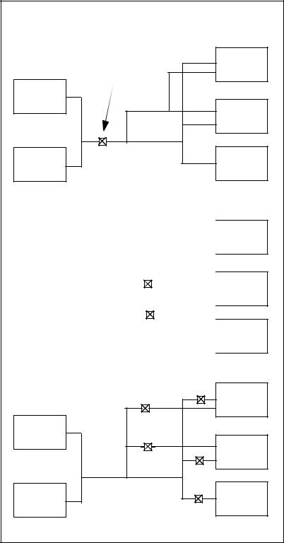
Auto-insertion of connect modules is done hierarchically. The connect modules are inserted based on the net disciplines and ports at each level of the hierarchy. The connect_mode split and merged are applied at each level of the hierarchy. This insertion supports the ability to coerce the placement of connect modules by declaring the disciplines of interconnect.
Figure 7-6 shows an example of auto-insertion with coercion.
167 |
Copyright © 2009 Accellera Organization, Inc. All rights reserved. |
Accellera |
|
Version 2.3.1, June 1, 2009 |
VERILOG-AMS |
|
module top; |
|
|
|
|
|
|
|
|
NetD |
|
|
|
|
|
|
|
|
|
|
||
|
|
|
|
|
|
|
|
|
|
|
|
|
|
|
|
|
|
|
|
|
||
|
|
|
|
|
|
|
|
|
|
|
|
|
|
|
|
|
|
|||||
|
module digital_blk (out); |
|
|
|
|
|
|
|
|
module mix |
(out); |
|||||||||||
|
module twoblks (out); |
|||||||||||||||||||||
|
|
|
|
|
|
|
|
|
|
|
|
|
|
|
|
|
|
|||||
|
|
|
|
|
|
|
|
|
|
|
|
|
|
|
|
NetC |
|
|||||
|
|
|
|
|
|
|
|
|
|
|
cmos1 |
|
||||||||||
|
cmos1 |
|
|
|
|
|
|
|
|
|
|
|
|
|
|
|
|
|
|
|
|
|
|
|
NetA |
|
|
|
|
|
|
|
|
(out); |
|
|
|
|
|
|
cmos1 |
|
|
||
|
|
|
|
|
|
|
|
|
|
|
|
|
|
|
|
|||||||
|
|
|
|
|
|
|
|
|
|
module blk3 |
|
|
|
|
|
|
|
|
|
|
||
module blk1 (out); |
|
|
|
|
|
|
|
|
|
|
|
|
|
|
||||||||
|
|
|
|
NetB |
|
|
|
|
|
|
|
|
|
|
|
|
|
|||||
|
|
|
|
|
|
|
|
|
|
|
|
|
|
module blk2 (out); |
||||||||
|
|
|
|
|
|
|
|
|
|
|
cmos1 |
|
|
|
|
|||||||
|
cmos1 |
|
|
|
|
|
|
|
|
|
|
|
|
|
|
|
|
|
|
|
|
|
|
|
|
|
|
|
|
|
|
|
(out); |
|
|
|
|
|
|
electrical |
|
||||
|
|
|
|
|
|
|
|
|
|
|
|
|
|
|
|
|
||||||
|
|
|
|
|
|
|
|
|
|
|
|
|
|
|
|
|
|
|||||
|
|
|
|
|
|
|
|
|
|
|
|
|
|
|
|
|
|
|||||
|
|
|
|
|
|
|
|
|
|
|
|
|
|
|
|
|
|
|
|
|
|
|
|
|
|
|
|
|
|
|
|
|
module blk4 |
|
|
|
|
|
|
|
|
|
|
||
module blk2 (out); |
|
|
|
|
|
|
|
|
|
(out); |
||||||||||||
|
|
|
|
|
|
|
|
module ablk |
||||||||||||||
|
|
|
|
|
|
|
|
|
|
|
|
|
|
|
|
|
|
|
|
|
|
|
// All digital modules have only output ports of discipline cmos1 connect cmos_d2a input cmos1 output electrical;
Figure 7-6: Auto-insertion with coercion
Case1: All interconnects are undeclared
—discipline resolution basic:
—merged: d2a at top.mix.blk2 and d2a at top.digital_blk (two connect modules).
—split: Same as merged.
—discipline resolution detail:
—merged: d2a at top.mix.blk2, d2a at top.digital_blk.(blk1-blk2), and d2a at top.digital_blk.twoblks (three connect modules).
—split: d2a at each of the five cmos1 blocks.
Case2: If NetB is declared as cmos1 and the remaining interconnect is undeclared
—discipline resolution basic:
—merged: d2a at top.mix.blk2 and d2a at top.digital_blk (two connect modules).
—split: Same as merged.
—discipline resolution detail:
—merged: d2a at top.mix.blk2, d2a at top.digital_blk.(blk1-blk2), and d2a at top.digital_blk.twoblks (three connect modules).
—split: d2a at top.mix.blk2, d2a at top.digital_blk.blk1, d2a at top.digital_blk.blk2, and d2a at top.digital_blk.twoblks (four connect modules).
7.8.2 Signal segmentation
Once a connect module has been selected it can not be inserted until it can be determined whether there should be one connect module per port or one connect module for all the ports on the net of a signal which match a given connect statement. Inserting multiple copies of the same connect module on one signal (i.e., between the signal and the multiple ports) has the effect of creating distinct segments of the signal with the same discipline at that level of the hierarchy.
Copyright © 2009 Accellera Organization, Inc. |
168 |
|
Accellera |
Analog and Mixed-signal Extensions to Verilog HDL |
Version 2.3.1, June 1, 2009 |
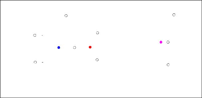
This segmentation of the signal which connects ports is only performed in the case of digital ports (i.e., ports with discrete-time domain or digital discipline). For analog (or continuous-time domain) disciplines, it is not desirable to segment the signal between the ports; i.e, there shall never be more than one analog node representing a signal. However, it can be desirable for the simulator’s internal representation of the signal to consist of various separate digital segments, each with its own connect module.
Figure 7-7 shows how to model the loading effect of each individual digital port on the analog node.
169 |
Copyright © 2009 Accellera Organization, Inc. All rights reserved. |
Accellera |
|
Version 2.3.1, June 1, 2009 |
VERILOG-AMS |
Insertion of connect instances creates distinct segments in a signal
connect instance
Analog
Analog
one LOGIC segment for all LOGIC ports
|
|
|
|
|
|
|
|
|
|
|
|
|
|
|
in |
|
||
|
|
|
|
|
|
|
|
|
|
|
|
|
|
|
|
|
|
|
|
|
|
|
|
|
|
|
|
|
|
|
|
|
|
out |
|||
Analog |
|
|
|
|
|
|
|
|
|
|
|
|
|
|
out |
|
||
|
|
|
|
|
|
|
|
|
|
|
|
|
|
|
||||
|
|
|
|
|
|
|
|
|
|
|
|
|
|
|
||||
|
|
|
|
|
|
|
|
|
|
|
|
|
|
|
|
|||
|
|
|
|
|
|
|
|
|
|
|
|
|
|
|
|
|
|
|
|
|
|
|
|
|
|
|
|
|
|
|
|
|
|
|
|
|
|
|
|
|
|
|
|
|
|
|
|
|
|
|
|
|
in |
|
||
|
|
|
|
|
|
|
|
|
|
|
|
|
|
|
|
|
|
|
|
|
|
|
|
|
|
|
|
|
|
|
|
|
|
|
|
|
|
|
|
|
|
|
|
|
|
|
|
|
|
|
|
|
|
|
|
|
Analog |
|
|
|
|
|
|
|
|
|
|
|
|
|
|
|
|
|
|
|
|
|
|
|
|
|
|
|
|
|
|
|
|
in |
|
|||
|
|
|
|
|
|
|
|
|
|
|
|
|
|
|
||||
|
|
|
|
|
|
|
|
|
|
|
|
|
|
|
|
|||
|
|
two LOGIC segments |
|
|||||||||||||||
|
|
(one for inputs, one for outputs) |
|
|||||||||||||||
|
|
|
|
|
|
|
|
|
|
|
|
|
|
|
|
|
|
|
|
|
|
|
|
|
|
|
|
|
|
|
|
|
|
|
|
|
|
|
|
|
|
|
|
|
|
|
|
|
|
|
|
|
|
|
|
|
|
|
|
|
|
|
|
|
|
|
|
|
|
|
|
|
|
|
|
Analog
Analog
a separate LOGIC segment for each LOGIC port
LOGIC
LOGIC
LOGIC
LOGIC
LOGIC
LOGIC
LOGIC
LOGIC
LOGIC
Figure 7-7: Signal segmentation by connect modules
Copyright © 2009 Accellera Organization, Inc. |
170 |