

Virtuoso XL Layout Editor User Guide
Using the Virtuoso Custom Placer
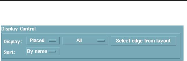
8.In the Display Control section of the Pin Placement form change the Display cyclic
field toPlaced to view the placed pins.
Assigning Pins to a Fixed Position
To assign pins to a fixed position within or on the boundary,
1.Choose Place – Pin Placement.
The Pin Placement form appears.
2.Change the Display to Unplaced and select a pin or a group of pins in the Pin Name list box.
You can also select a pin from the layout and have it highlighted in the list box. Select Link to Layout and click anywhere in the layout window. Select a pin or a group of pins and the pin is highlighted in the list box.
3.Specify an Edge and change the Location to either Fix after Placing.
The Fix after Placing option places the pin at a location on the boundary and then fixes the pin. Fixed pins are not allowed to move the pin from the fixed location.Usermovable pins can be moved to another location and then they are fixed at the new location.
4.Click Apply.
The pin moves to the specified position in the layout. TheLocation cyclic field shows the placed pin position coordinates. Coordinates refer to the center of the pin.
5.Repeat Step 3 through Step 5 for each fixed pin.
You can click Default to delete all current pin placements and return all pins to their unplaced positions below the design boundary.
December 2002 |
280 |
Product Version 5.0 |
Virtuoso XL Layout Editor User Guide
Using the Virtuoso Custom Placer
Assigning Pins to a Specific Fixed Position
1.Select Edit – Move and move an unplaced pin to the desired location.
2.Select/re-select the pin on the Pin Placement form.
3.In the Location cyclic field select theFix at Placed Location option and click Apply.
The pin is now fixed at the desired location and is not aligned with any edge.
Note: You can also optionally assign the pin to an edge right after step 2 and then click Apply in the Pin Placement form. In this case the pin is fixed to the location but the pins width plus the pins design rules will be projected on the aligned edge.
This projection leaves open a channel on the aligned edge for the fixed pin to facilitate better routing from outside the boundary.
Railing Pins
1.Select an unplaced pin to be railed and specify an Edge. Click Apply to place the pin on the boundary.
2.Select the pin to be railed and click either HRail for a horizontal rail or VRail for a vertical rail.
When a pin is changed into a rail, it becomes aligned with two edges of the boundary.
For a horizontal rail, the alignment is to the left and right edges. For a vertical rail, the alignment is the bottom and top edges. The rail will stretch with the boundary in a constrained editing mode.
Important
The Pin Placement form does not distinguish layer information when the pins are placed on the boundary edges. If you have a metal 2 pin to be railed that occupies the same location as a metal1 pin, then you will not be allowed to rail the pin.
3.To view the alignment constraints of the rail select CIW-Tools – Constraint Manager.
4.Change the Select Entity to Geometric Constraints and click Alignment. The pin placement is displayed. The pin constraints created from the Pin Placement form can only be viewed but not edited from the Constraint Manager form.
5.To unrail a pin select the pin in the Pin Placement form and select the un(H/V)Rail option. The unrailed pin is returned to the original size and edge, regardless of the railing direction.
December 2002 |
281 |
Product Version 5.0 |

Virtuoso XL Layout Editor User Guide
Using the Virtuoso Custom Placer
Loading the Template File
1.Click Template file and the Load Template form appears.
2.Click on the directories in the left list box to descend into your file hierarchy until you reach the name of the template file to use.
The left and right arrows at the right side of the form let you go up and down in the file hierarchy.
3.Click on the name of the template file in the right list box to enter it in theName field.
4.In the Load sections area, turn on the sections of the template file you want to load (I/O Pins).
5.In the Existing data area, turn on Merge if you want to merge the information from the template with the placement data already in virtual memory or turn on Replace if you want to replace the placement data in virtual memory with different placement data in a template file.
6.Click OK.
Assigning Spacing Between Pins
To set the exact distance between two or more ordered pins, or between the pins of a bus (iterated) pin using the Pin Placement form,
1.Change the Display cyclic field to display the type of pins you want to assign spacing to.
Note: A pitch value may only be set for ordered pins. The pitch value field on the form becomes active when either a set of ordered and placed pins are selected in the list box, or a set of unplaced pins are selected and a value is entered in the Order field.
2.Highlight the pins in the Pin Name list box. To highlight multiple pins Shift click on each of the pin names.
3.Specify the center to center spacing of pins in the Pitch field.
Important
Press the Tab key to activate the Apply button.
The pitch will be valid if the pins are on the same boundary edge.
4.To list the pins of a bus (iterated) pin individually highlight the bus pin and click Expand in the Iterated Pins section.
December 2002 |
282 |
Product Version 5.0 |