


USB System Architecture
How Transactions Are Generated
USB 1.x system implementations generate USB transactions by fetching and executing a linked list of data structures (called transfer descriptors) from memory. Each transfer descriptor defines a USB transaction that software has requested and scheduled for the purpose of accessing a USB device. For example, one transfer descriptor may specify that a USB keyboard be accessed to check whether a keystroke has occurred, while another descriptor may specify a data transfer to a printer. In this example, the keyboard is a low-speed device and the printer is accessed at full speed.
What the Descriptors Contain
Each transfer descriptor contains information that describes a transaction to be performed. The primary information includes:
•The USB device address
•The type of transaction to be performed (read or write)
•The transfer size
•Speed of the transaction
•The location of the memory data buffer (a full buffer containing data to be sent to the USB device or an empty buffer where data read from the USB device is to be placed)
With this information the USB host controller can perform the specified transaction. In the personal computer arena two host controller interfaces were designed for USB 1.x devices: the Universal Host Controller Interface (UHCI) and Open Host Controller Interface (OHCI). Each accomplishes the same jobs but in different ways, and each has its own transfer descriptor definition. See Figure C-4 on page 470 for details on the transfer descriptor definition for the UHCI host controller or Figure D-6 on page 486 for the OHCI host controller.
How the Transfer Descriptors Are Fetched
The linked list of descriptors is sometimes called a transaction list or frame list. During a 1ms interval (called a frame), the host fetches and executes a series of descriptors. Figure 2-5 on page 31 and Figure 2-6 on page 32 provide a conceptual view of the steps taken by the host controller when it fetches and executes transactions from the frame list. In these examples, the frame list contains transfer descriptors that access a USB keyboard and a USB printer. Note that these examples do not deal with the entire USB protocol, but rather deal only with the conceptual process of transaction generation across the USB.
30
Chapter 2: The Big Picture
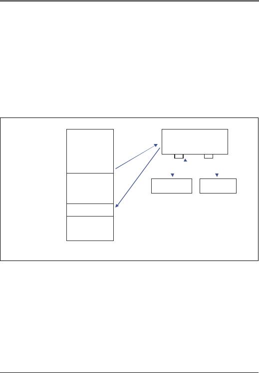
The first example depicts a keyboard being polled by software to check if a key has been pressed. The direction of data flow in USB is specified with respect to the host. Since data is being read by the host, the transaction is termed an IN transaction. Figure 2-5 illustrates the sequence of events associated with the IN transaction from the keyboard.
Previously the keyboard’s USB driver has requested that the keyboard be polled periodically to determine if the user has pressed a key. The driver also supplies a memory buffer location where the keyboard data is to be returned. This request has resulted in the host software creating a transfer descriptor in memory (Transaction 1 in Figure 2-5) that describes the USB polling operation. The
Figure 2-5: Conceptual View of Transaction Generation — Example 1
7UDQVIHU |
|
|
^ |
7UDQVDFWLRQ7UDQVDFWLRQ |
|
|
||
'HVFULSWRUV |
7UDQVDFWLRQ |
|
|
|
. % 'DWD |
|
|
|
0HPRU\
|
|
|
+RVW &RQWUROOHU |
|
||||||||
|
|
|
/ 6 WUDQVDFWLRQ |
|
||||||||
|
|
|
|
|
|
|
|
|
|
|
||
|
|
|
|
|
|
|
|
|
|
|
|
|
|
|
|
|
|
|
|
|
|||||
|
|
|
|
|
|
|
|
|||||
|
|
|
|
|
|
|||||||
|
|
|
|
|
|
|
|
|||||
|
.H\ERDUG |
|
3ULQWHU |
|||||||||
|
|
|
|
|
|
|
|
|
|
|
|
|
/6 7DUJHW
+ & IHWFKHV GHVFULSWRU
+ & JHQHUDWHV ,1 WUDQVDFWLRQ
. % UHWXUQV G D WD
+ & WUDQVIHUV . % GDWD WR PHPRU
host controller fetches transaction 1 and decodes the descriptor and executes the requested IN transaction. The keyboard returns data to the host controller, which in turn places the data into the keyboard data area in memory. The pointer to the keyboard data buffer is included within the transfer descriptor. The keyboard software driver reads the keyboard data buffer to acquire the data.
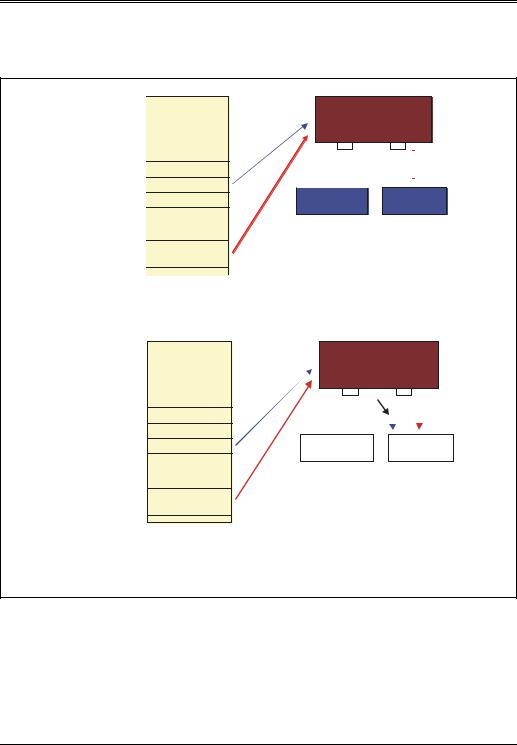
The second and third descriptors define transactions that send data to the USB printer. The direction of data flow in this case is OUT from the host. Figure 2-6 on page 32 illustrates the sequence of events when executing these transactions.
31
USB System Architecture
Figure 2-6: Conceptual View of Transaction Generation — Example 2
7UDQVIHU |
^ |
7UDQVDFWLRQ7UDQVDFWLRQ |
'HVFULSWRUV |
7UDQVDFWLRQ |
|
|
|
3ULQWHU 'DWD |
|
|
Memory |
Transfer |
^ |
TransactionTransaction 12 |
Descriptors |
7UDQVDFWLRQ |
3ULQWHU 'DWD
Memory
+RVW &RQWUROOHU
|
) 6 WUDQVDFWLRQ |
|


.H\ERDUG 3ULQWHU
)6 7DUJHW
+ & IHWFKHV GHVFULSWRU
+ & JHQHUDWHV )6 287 WUDQVDFWLRQ
+ & IHWFKHV SULQWHU GDWD IURP PHP
+ & VHQGV GDWD WR SULQWHU
Host Controller
|
) 6 WUDQVDFWLRQ |
||||||
1 |
|
|
2 |
|
|
4 |
|
|
|
|
|||||
|
|
|
|
|
|
|
|
|
|
|
|
|
|
|
|
|
Keyboard |
|
Printer |
||||
3 |
|
|
|
|
|
|
|
|
|
|
|
Target |
|||
|
|
|
|
|
|||
+ & IHWFKHV GHVFULSWRU
+ & JHQHUDWHV )6 287 WUDQVDFWLRQ
+ & IHWFKHV QH[W EORFN RI SULQWHU GDWD IURP PHPRU\
+ & VHQGV GDWD WR SULQWHU
32
Chapter 2: The Big Picture
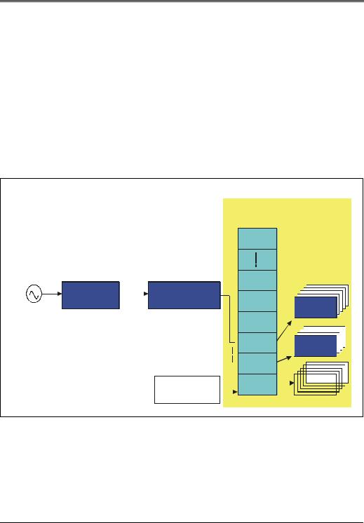
Frame Generation
Figure 2-7 illustrates how the controller fetches each frame list on 1ms intervals. Note that each 1ms frame consists of 12,000 bit times at the 12Mb/s bit rate, during which transactions are performed. A 12MHz clock increments a counter that generates a carry output when the count reaches 12,000, thereby creating a 1kHz clock (1ms periods). The carry output increments another counter containing a frame number that is used as an address location to fetch the first transfer descriptor in a linked list of descriptors. Each transfer descriptor contains a link address to the next descriptor in the list. In this way, each descriptor in the list is fetched and executed, resulting in a series of USB transactions during the current frame.
Figure 2-7: Conceptual View of 1ms Frame Generation
0HPRU\
|
|
|
|
7 !97 |
|
|
|
|
7 !97 |
4:3907 |
|
|
)UDPH 1XPEHU |
|
|
1ms |
&RXQWHU |
7 !97 |
|
12MHz
7 !97  7 !97
7 !97


 % 8
% 8


 % 8
% 8 


|
|
|
|
7 !97 |
|
|
|
|
|
|
||||||
|
|
|
|
|
|
|
|
|
|
|||||||
|
|
|
|
|
|
|
||||||||||
|
|
|
|
|
|
|
|
|
|
|
|
|
|
|||
|
|
|
|
|
|
|
|
|
|
|
|
|
|
|
|
|
|
|
|
|
|
|
|
|
|
|
|
|
|
|
|
|
|
)UDPH /LVW |
|
|
|
7 !97 |
|
|
|
|
|
|
% 8 |
|
|
|
|
|
|
||||||||||||||||
|
|
|
|
|
|
|
|
|
||||||||
|
|
|
|
|
|
|
|
|
|
|
|
|
|
|||
|
|
|
|
|
|
|
|
|
|
|
|
|
|
|
|
|
%DVH $GGU |
|
|
|
|
|
|
|
|
|
|
|
|
|
|
|
|
|
|
|
|
|
|
|
|
|
|
|
|
|
|
|
||
|
|
|
|
|
|
|
|
|
|
|
|
|
|
|
|
|
33