

- •Single-User License Agreement
- •Chapter 1: Design Goals of USB
- •Chapter 2: The Big Picture
- •Chapter 3: Cables and Connectors
- •Chapter 4: USB Cable Power Distribution
- •Chapter 5: LS/FS Signaling Environment
- •Chapter 6: LS/FS Transfer Types & Scheduling
- •Chapter 7: Packets & Transactions
- •Chapter 8: Error Recovery
- •Chapter 9: USB Power Conservation
- •Chapter 10: Overview of HS Device Operation
- •Chapter 11: The High-Speed Signaling Environment
- •Chapter 12: HS Transfers, Transactions, & Scheduling
- •Chapter 13: HS Error Detection and Handling
- •Chapter 14: HS Suspend and Resume
- •Chapter 15: HS Hub Overview
- •Chapter 16: 2.0 Hubs During HS Transactions
- •Chapter 17: 2.0 Hubs During LS/FS Transactions
- •Chapter 18: Configuration Process
- •Chapter 19: USB Device Configuration
- •Chapter 20: Hub Configuration
- •Chapter 21: Device Classes
- •Chapter 22: Overview of USB Host Software
- •Appendix A: Standard Device Requests
- •Appendix B: Hub Requests
- •Appendix C: Universal Host Controller
- •Appendix D: Open Host Controller
- •About This Book
- •The MindShare Architecture Series
- •Cautionary Note
- •Specifications This Book is Based On
- •Organization of This Book
- •Part One: Overview of USB 2.0
- •Part Two: Low- & Full-Speed Device Operation
- •Part III: High-Speed Device Operation
- •Part IV: USB 2.0 Hub Operation with LS/FS/HS Devices
- •Part VI: USB Software Overview
- •Appendices
- •Who Should Read this Book
- •Prerequisite Knowledge
- •Documentation Conventions
- •Hexadecimal Notation
- •Binary Notation
- •Decimal Notation
- •Bits Versus Byte Notation
- •Identification of Bit Fields (logical groups of bits or signals)
- •Visit Our Web Page
- •We Want Your Feedback
- •Shortcomings of the Original PC I/O Paradigm
- •Limited System Resources
- •Interrupts
- •I/O Addresses
- •Non-shareable Interfaces
- •End User Concerns
- •Cable Crazed
- •Installation and Configuration of Expansion Cards
- •No Hot Attachment of Peripherals
- •Cost
- •The USB Paradigm
- •Enhanced System Performance
- •Hot Plug and Play Support
- •Expandability
- •Legacy Hardware/Software Support
- •Low Cost
- •Summary of Key USB Features
- •How to Get the USB Specifications
- •2 The Big Picture
- •Overview
- •USB 1.x Systems and Devices
- •Low-Speed and Full-Speed Devices
- •How Transactions Are Generated
- •What the Descriptors Contain
- •How the Transfer Descriptors Are Fetched
- •Frame Generation
- •Sharing the Bus
- •Bandwidth Consideration Summary
- •2.0 Systems and Devices
- •Low-Speed and Full-Speed Devices in a 2.0 System
- •Example 2.0 Host Controller Support for LS/FS Devices
- •High-Speed Devices in a 2.0 System
- •High-Speed Devices Attached to 1.x Ports
- •High-Speed Transactions and Microframe Generation
- •High-Speed Bandwidth Summary
- •The Players
- •USB Client Drivers
- •USB Bus Driver
- •USB Host Controller Driver
- •USB Host Controller/Root Hub
- •The Host Controller
- •The Root Hub
- •USB Hubs
- •Hub Controller
- •Hub Repeater
- •Hub’s Role in Configuration
- •USB Devices
- •High-Speed Devices
- •Full-Speed Devices
- •Low-Speed Devices
- •USB Communications Model
- •Communications Flow
- •Transfers, IRPs, Frames, and Packets
- •Transfers
- •The USB Driver, IRPs, and Frames
- •The Host Controller Driver and Transactions
- •The Host Controller and Packets
- •Device Framework (how devices present themselves to software)
- •Device Descriptors
- •Device Framework
- •USB Bus Interface Layer
- •USB Device Layer
- •Function Layer
- •USB Peripheral Connection
- •Full-Speed Hubs
- •High-Speed Hubs
- •High-Speed Devices
- •Topology
- •The Connectors
- •Series A Connectors
- •Series B Connectors
- •Cables
- •Low-Speed Cables
- •Cable Power
- •Electrical and Mechanical Specifications
- •USB Power
- •Hubs
- •Current Budget
- •Over-Current Protection
- •Voltage Drop Budget
- •Power Switching
- •Bus-Powered Hubs
- •Power During Hub Configuration
- •Bus-Powered Hub Attached to 500ma Port
- •Bus-Powered Hub Attached to 100ma Port
- •Bus-Powered Hub Attached to Port with >100ma but <500ma
- •Current Limiting
- •Bus-Powered Devices
- •Low-Power Devices
- •High-Power Devices
- •Power During Configuration
- •Insufficient Port Power
- •Self-Powered Hubs
- •Power During Configuration
- •Locally Powered Bus Interface
- •Hybrid Powered Device
- •Current Limiting
- •Self-Powered Devices
- •Power During Configuration
- •Locally Powered Bus Interface
- •Hybrid Powered Device
- •Overview
- •Detecting Device Attachment and Speed Detect
- •Full-Speed Device Connect
- •Low-Speed Device Connect
- •Detecting Device Disconnect
- •Bus Idle
- •Device RESET
- •Differential Signaling
- •Differential Drivers
- •Full-Speed Drivers
- •Low-Speed Drivers
- •Hub Driver Characteristics
- •Differential Receivers
- •Start of Packet (SOP)
- •End of Packet (EOP)
- •Single-Ended Receivers
- •NRZI Encoding
- •Bit Stuffing
- •Summary of USB Signaling States
- •Overview
- •Client Initiates Transfer
- •Communications Pipes
- •Communication Initiated by I/O Request Packets
- •Frame-Based Transfers
- •Transfer Types
- •Isochronous Transfers
- •Direction of Transfers
- •Service Period
- •Bandwidth Allocation
- •Error Recovery
- •Establishing Synchronous Connections
- •The Problem with Isochronous Transfers
- •The Feedback/Feed Forwarding Solution
- •Synchronization Types
- •Source/Sink Combinations and Synchronization Methods
- •How Endpoints Report Their Synchronization Capabilities
- •Feedback Data
- •Association Between Data Endpoint and Feedback Endpoint
- •Interrupt Transfers
- •Service Period
- •Bus Bandwidth Allocation
- •Error Recovery
- •Control Transfers
- •Bus Bandwidth Allocation
- •Error Recovery
- •Bulk Transfers
- •Bus Bandwidth Allocation
- •Error Recovery
- •Overview
- •Packets — The Basic Building Blocks of USB Transactions
- •Synchronization Sequence
- •Packet Identifier
- •Packet-Specific Information
- •Cyclic Redundancy Checking (CRC)
- •End of Packet (EOP)
- •Token Packets
- •SOF Packet
- •IN Packet
- •OUT Packet
- •SETUP Packet
- •Data Packets — DATA0 and Data1
- •Handshake Packets
- •Preamble Packet
- •Transactions
- •IN Transactions
- •IN Transaction Without Errors
- •IN Transaction with Errors
- •IN Transaction with No Interrupt Pending/Target Busy
- •IN Transaction with Target Stalled
- •IN Transaction During Isochronous Transfer
- •OUT Transactions
- •OUT Transaction Without Data Packet Errors
- •OUT Transaction with Errors
- •OUT Transaction — Target Unable to Accept Data
- •OUT Transaction With Target Stalled
- •OUT Transaction During Isochronous Transfer
- •Setup Transactions/Control Transfers
- •Two Stage Control Transfer
- •Three Stage Control Transfer with IN Data Stage
- •Three Stage Control Transfer with OUT Data Stage
- •Control Transfers With Errors
- •8 Error Recovery
- •Overview
- •Packet Errors
- •PID Checks
- •CRC Errors
- •Bit Stuff Errors
- •Packet-Related Error Handling
- •Token Packet Errors
- •Data Packet Errors
- •Handshake Packet Errors
- •Bus Time-Out
- •False EOPs
- •False EOP During Host Transmission
- •False EOP During Target Transmission
- •Data Toggle Errors
- •Data Toggle Procedure Without Errors
- •Data Toggle during OUT Transactions
- •Data Toggle During IN Transactions
- •Data Toggle Procedure with Data Packet Errors
- •Data Toggle and Data Packet Errors — OUT Transactions
- •Data Toggle and Data Packet Errors — IN Transactions
- •Data Toggle With Handshake Packet Error — IN Transaction
- •Special Case: Data Toggle During Control Transfer
- •Babbling Devices
- •Loss of Activity (LOA)
- •Babble/LOA Detection and Recovery
- •Frame Timer
- •Host to Hub Skew
- •Hub Repeater State Machine
- •Isochronous Transfers (Delivery Not Guaranteed)
- •Interrupt Transfer Error Recovery
- •Bulk Transfer Error Recovery
- •Control Transfer Error Recovery
- •Power Conservation — Suspend
- •Device Response to Suspend
- •Hub Response to Suspend
- •Global Suspend
- •Initiating Global Suspend
- •Resume from Global Suspend
- •Resume Initiated by Host
- •Remote Wakeup from Device
- •Remote Wakeup via Hub Port Event
- •Selective Suspend
- •Initiating Selective Suspend
- •Resume from Selective Suspend
- •Host Initiated Selective Resume
- •Selective Wakeup from Device
- •Selective Suspend When Hub is Suspended
- •Device Signals Resume
- •Port Receives Connect or Disconnect
- •Selective Suspend Followed by Global Suspend
- •Resume via Reset
- •Hub Frame Timer After Wakeup
- •Overview
- •New High-Speed Device Features
- •1.x USB Device Support
- •The 2.0 Host Controller
- •Overview
- •Detecting High-Speed Device Attachment
- •Initial Device Detection
- •Device Reset and the Chirp Sequence
- •High-Speed Interfaces Idled
- •High-Speed Differential Signaling
- •Impedance Matching
- •High-Speed Driver Characteristics
- •High-Speed Idle
- •High-Speed Differential Receivers
- •High-Speed Driver/Receiver Compliance Testing
- •Activating Test Mode
- •The Test Setup
- •Eye Pattern Tests
- •High-Speed Start of Packet & Synchronization Sequence
- •High-Speed End of Packet (EOP)
- •Detection of High-Speed Device Removal
- •High-Speed RESET and Suspend
- •Signaling RESET
- •Signaling Suspend
- •Differentiating Between RESET and Suspend
- •Overview
- •High-Speed Transaction Scheduling
- •Microframes
- •Theoretical HS Bandwidth
- •Periodic Transfers
- •High-Speed Isochronous Transfers
- •Maximum Packet Size
- •Isochronous Bandwidth/Performance
- •Isochronous Transaction Errors
- •High-Speed Interrupt Transfers
- •Maximum Packet Size
- •Interrupt Bandwidth
- •Interrupt Transaction Errors
- •High-Bandwidth Transactions
- •Detecting High-Bandwidth Endpoints and Packet Size
- •Isochronous High-Bandwidth Scheduling and Protocol
- •High Bandwidth Interrupt Transactions
- •High Bandwidth Throughput
- •Non-Periodic Transfers
- •High-Speed Bulk Transfers
- •Maximum Packet Size
- •Bulk Bandwidth
- •Bulk Transactions Errors
- •High-Speed Control Transfers
- •High-Speed Control Bandwidth
- •Ping Transactions
- •The Problem
- •The Solution
- •The Ping Protocol
- •Overview
- •High-Speed Bus Time-out
- •False EOP
- •HS Babbling Device Detection
- •Overview
- •Entering Device Suspend
- •Device Resume
- •15 HS Hub Overview
- •Overview
- •USB 2.0 Hub Attached to High-Speed Port
- •High-Speed Transactions
- •USB 2.0 Hub Attached to Full-Speed Port
- •Overview
- •High-Speed Hub Repeater
- •Receiver Squelch
- •Re-clocking the Packet
- •Port Selector State Machine
- •Elasticity Buffer
- •The Repeater State Machine
- •Overview
- •The Structure of Split Transactions
- •Isochronous Split Transaction Examples
- •Example Split Isochronous OUT Transaction
- •Example Split Isochronous IN Transaction
- •Example Split Transactions with Data Verification
- •Split OUT Sequence
- •Split IN Sequence
- •The Split Token Packet
- •The Transaction Translator
- •The Major Elements of the Transaction Translator
- •High-Speed Handler
- •Periodic Transfer Start-Split Buffer
- •Periodic Complete-Split Buffer
- •Bulk/Control Buffers
- •Low-Speed/Full-Speed Handler
- •Split Transaction Scheduling
- •Split Transaction Scheduling Example
- •SOF Packets
- •Host Delivers Isochronous Start Split
- •Host Delivers Interrupt Start Split
- •Host Issues Complete-Split to Fetch Isochronous IN Data
- •Host Fetches Interrupt OUT Completion Status
- •Host Continues to Fetch Isochronous IN Data
- •Transaction End
- •High-Speed Scheduling Can Include Other Transactions
- •Single versus Multiple Transaction Translators
- •Periodic Split Transactions
- •Periodic Split Transaction Pipeline
- •High Speed Handler Receives Start Split
- •Start-Split Buffer
- •Low-Speed/Full-Speed Handler
- •Complete-Split Buffer
- •Isochronous OUT Split Transaction Sequence
- •Isochronous OUT Start Split
- •Handling CRC16 During Split Isochronous OUT Transactions
- •Isochronous IN Split Transaction Sequence
- •Isochronous IN Start Split
- •Isochronous IN Complete Split
- •Handling CRC16 During Split Isochronous IN Transactions
- •Interrupt Split OUT Transaction Sequence
- •Interrupt OUT Start Split Sequence
- •Interrupt OUT Complete Split Sequence
- •Interrupt IN Split Transaction Sequence
- •Interrupt IN Start Split Sequence
- •Interrupt IN Complete Split Sequence
- •Handling CRC16 During Split Interrupt IN Transactions
- •Non Periodic Split Transactions
- •Non-Periodic Split Transaction Pipeline
- •High Speed Handler
- •Non-periodic Buffers
- •Low-/Full-Speed Handler
- •Bulk/Control Split OUT Transaction Sequence
- •Bulk/Control OUT Start Split Sequence
- •Bulk/Control OUT Complete Split Sequence
- •Bulk/Control Split IN Transaction Sequence
- •Bulk/Control IN Start Split Sequence
- •Bulk/Control IN Complete Split Sequence
- •Overview
- •The Configuration Software Elements
- •USB Host Controller Driver
- •Configuration Software
- •Default Control Pipe
- •Resource Management
- •Device Client Software
- •Root Hub Configuration
- •Each Device Is Isolated for Configuration
- •Reset Forces Device to Default Address (zero)
- •Host Assigns a Unique Device Address
- •Host Software Verifies Configuration
- •Power Requirements
- •Bus Bandwidth
- •Configuration Value Is Assigned
- •Client Software Is Notified
- •Overview
- •Summary of Configuration Process
- •How Software Detects Device Attachment & Speed
- •Polling the Status Change Endpoint
- •Getting Port Status
- •Resetting the Port
- •Reading and Interpreting the USB Descriptors
- •The Standard Descriptors
- •How Software Accesses the Descriptors
- •Device Descriptor
- •Class Code Field
- •Maximum Packet Size Zero
- •Manufacturer, Product, Serial Number
- •Number of Configurations
- •Device Qualifier Descriptor
- •Configuration Descriptors
- •Number of Interfaces
- •Configuration Value
- •Attributes and Maximum Power
- •Other Speed Configuration Descriptor
- •Interface Descriptors
- •Interface Number and Alternate Setting
- •Number of Endpoints
- •Interface Class and Subclass
- •Protocol
- •Endpoint Descriptors
- •Device States
- •Attached State
- •Powered State
- •Default State
- •Addressed State
- •Configured State
- •Suspend State
- •Client Software Configuration
- •Configuring the Hub
- •The Default Pipe
- •The Status Change Pipe
- •Reading the Hub’s Descriptors
- •1.x Hub Descriptors
- •Hub’s Standard Device Descriptor
- •Hub Configuration Descriptor
- •Number of Interfaces
- •Configuration Value
- •Maximum Bus Power Consumed
- •Hub Interface Descriptor
- •Status Endpoint Descriptor
- •Status Change Endpoint Address/Transfer Direction
- •Transfer Type
- •Maximum Data Packet Size
- •Polling Interval
- •Hub Class Descriptor
- •Power Switching Mode Implemented
- •Compound Device or Hub Only
- •Over-Current Protection Mode
- •Power On to Power Good Delay
- •Maximum Bus Current for Hub Controller
- •Device Removable/Non-removable
- •Port Power Mask
- •High-Speed Capable Hub Descriptors
- •Descriptors When Hub Is Operating at Full Speed
- •The 2.0 Hub’s Class-Specific Descriptor
- •Powering the Hub
- •Checking Hub Status
- •Detecting Hub Status Changes
- •Reading the Hub Status Field
- •Reading Port Status
- •Enabling the Device
- •Summary of Hub Port States
- •21 Device Classes
- •Overview
- •Device Classes
- •Audio Device Class
- •Standard Audio Interface Requirements
- •Synchronization Types
- •Audio Class-Specific Descriptors
- •Audio Class-Specific Requests
- •Communications Device Class
- •Communications Device Interfaces
- •Communications Class-Specific Descriptors
- •Communications Class-Specific Requests
- •Display Device Class
- •The Standard Display Device Class Interface
- •Display Device-Specific Descriptors
- •Device-Specific Requests
- •Mass Storage Device Class
- •Standard Mass Storage Interface
- •Control Endpoint
- •Bulk Transfer Endpoints
- •Interrupt Endpoint
- •General Mass Storage Subclass
- •CD-ROM Subclass
- •Tape Subclass
- •Solid State Subclass
- •USB Software
- •Function Layer
- •Device Layer
- •Interface Layer
- •The Software Components
- •USB Driver (USBD)
- •Configuration Management
- •USB Elements Requiring Configuration
- •Allocating USB Resources
- •Verifying Power
- •Tracking and Allocating Bus Bandwidth
- •Bus Bandwidth Reclamation
- •Data Transfer Management
- •Providing Client Services (The USB Driver Interface)
- •Pipe Mechanisms
- •Client Pipe Requirements
- •Command Mechanisms
- •Appendix
- •Overview
- •Standard Device Requests
- •Set/Clear Feature
- •Device Remote Wakeup
- •Endpoint Stall
- •Set/Get Configuration
- •Set/Get Descriptor
- •Set/Get Interface
- •Get Status
- •Device Status
- •Self-Powered Bit
- •Remote Wakeup Bit
- •Port Test Bit
- •Endpoint Status
- •Sync Frame
- •Device Tests
- •High-speed Driver/Receiver Compliance Testing
- •Activating Test Mode
- •Overview
- •Hub Request Types
- •Standard Requests and Hub Response
- •Hub Class Requests
- •Get/Set Descriptor Request
- •Get Hub Status Request
- •Hub Status Fields
- •Local Power Status
- •Over-Current Indicator
- •Hub State Change Fields
- •Local Power Status Change
- •Over-Current Indicator Change
- •Set/Clear Hub Feature Request
- •Hub Local Power Change Request
- •Hub Over-Current Change Request
- •Get Port Status Request
- •Port Status Fields
- •Current Connect Status Field
- •Port Enabled/Disabled
- •Suspend
- •Over-Current Indicator
- •Reset
- •Port Power
- •Low-Speed Device Attached
- •High-Speed Device Attached
- •Port Test
- •Port Indicator Control
- •Port Change Fields
- •Current Status Change
- •Port Enable/Disable Change
- •Suspend Change (Resume Complete)
- •Over-Current Indicator Change
- •Reset Complete
- •Set/Clear Port Feature
- •Port Test Modes
- •Get Bus State
- •Overview
- •Universal Host Controller Transaction Scheduling
- •Universal Host Controller Frame List Access
- •UHC Transfer Scheduling Mechanism
- •Bus Bandwidth Reclamation
- •Transfer Descriptors
- •Queue Heads
- •UHC Control Registers
- •Overview
- •Open Host Controller Transfer Scheduling
- •The Open Host Controller Transfer Mechanism
- •The ED and TD List Structure
- •Interrupt and Isochronous Transfer Processing
- •Control and Bulk Transfer Processing
- •The Done Queue
- •Interrupt Transfer Scheduling
- •Endpoint Descriptors
- •Transfer Descriptors
- •General Transfer Descriptor
- •Isochronous Transfer Descriptor
- •The Open Host Controller Registers
- •Index

13 HS Error
Detection and
Handling
The Previous Chapter
The previous chapter introduces the changes brought about by the USB 2.0 specification. The transfers defined in USB 1.0 are also used in 2.0 implementations and have the same primary characteristics in the high-speed environment. However, some changes have been made such as new packet sizes. Furthermore, new features have been added to the high-speed environment such as high-bandwidth transfers and the ping protocol. These and other changes are reviewed in this chapter.
This Chapter
Error detection and handling during high-speed transactions are very similar in concept to the lowand full-speed error detection methods. However, due to the faster clock rates, several of the timing parameters must be changed to support error detection implementations such as time-out values and babble detect.
The Next Chapter
This chapter discusses the changes required for high-speed devices to use the full-speed suspend and resume protocol and signaling conventions.
Overview
Error checking and recovery in the high-speed environment can be summarized as follows:
•same packet error detection as performed by lowand full-speed devices.
•transaction time-outs consist of the same round-trip delays, but the some of
265

USB System Architecture
the delays have been changed and delay timing is specified by high-speed bit times rather than lowor full-speed bit times.
•EOF1 and EOF2 babbling device detection uses the same principles as employed by 1.x hubs, but the EOF points are also referenced to high-speed bit times.
•packet error checking and reporting is modified as necessary to support split transactions.
High-Speed Bus Time-out
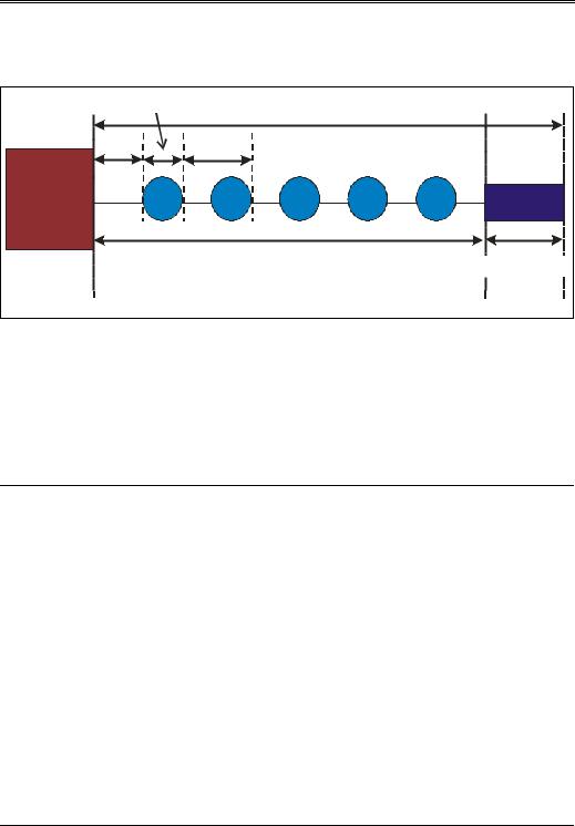
Like in the 1.x environment, high-speed devices report packet errors by remaining silent when a response is expected. No response is a positive indication to the device that is awaiting a return packet that the transfer has failed. The amount of time that a device waits for a response before detecting an error is specified by the worst-case round-trip delay between the host and target device. Figure 13-1 on page 267 depicts the topology that represents the worst delay. The round-trip delay is specified in high-speed bit times and is based on following:
•The maximum number of cable hops between host and device = 6
•Maximum number of hubs = 5
•Maximum response time of function = 192 high-speed bit times
•Maximum cable propagation delay = 26ns
•Maximum hub delay = 36 bit times + 4ns
The total round-trip delay is calculated as:
•12 cable crossings * 26ns = 312ns (~150 HS bit times)
•10 hub crossings * 36 bit times + 4ns = 360 bit times + 40ns (~379 HS bit times)
•Maximum response time of function = 192 HS bit times
Total delay = 721 HS bit times
The specification requires that the time-out not occur any earlier than 736 HS bit times and any later than 816 HS bit times.
266
Chapter 13: HS Error Detection and Handling
Figure 13-1: Worst-Case Round Trip Delay Between Host and Function
|
36 bit times +4 n s |
7RWDO 'HOD\ |
+6 ELW W |
|
L |
|||
|
|
|
|
|||||
|
26 ns |
36 bit times |
|
|
|
|
|
|
|
+30ns |
|
|
|
|
|
||
Host |
Hub 1 |
|
Hub 2 |
Hub 3 |
Hub 4 |
Hub 5 |
Function |
|
Controller |
|
|||||||
|
|
|
|
|
|
|
|
|
|
Total Cable Delay = 150 + 379, or 529 HS bit times |
ELW WLPHV |
||||||
When the host or device transmits a packet requiring a response, a counter is started when the packet is completely transmitted and the counter stops when the start of the return packet is detected. The counter starts when the data lines return to the squelch level indicating packet end, and stops when the data lines leave the squelch level, indicating packet start. If the counter exceeds the specified time-out period, then an error is flagged. Behavior beyond this point is identical to the lowand full-speed implementations.
False EOP
High-speed EOPs are detected by a bit-stuffing error. The specification states that a receiver is required to interpret any bit-stuffing error as an EOP. If a non EOP bit-stuffing error occurs during the transmission of a packet, a false EOP is detected along with a CRC error.
Reaction to a false EOP by the host or device is the same for low-, full-, and high-speed operation, with one exception: host behavior after detecting a false EOP. Below is a summary of host behavior in the lowand full-speed environment and in the high-speed environment:
•In the lowor full-speed environment when a false EOP is detected, the host controller waits for the packet to end and then waits for an additional 16 bit times before sending the next packet downstream. The 16 bit time delay ensures that the transmitting device will time out and recognize that an
267

USB System Architecture
error has occurred in the packet just transmitted.
•In the high-speed environment if the host receives a corrupted high-speed data packet (including false EOP), it ignores any data until the data lines return to the squelch level. Upon detecting squelch, the next token packet can be sent immediately with normal inter-packet delays. Note that during high-speed operation, the host is not required to wait for the device to detect time-out before sending the next packet. In this case, the device has transferred data to the host and is unaware that a packet error has occurred, so the device is expecting a handshake packet that acknowledges successful transfer of data. However, the next packet sent by the host is a token packet that does not target the endpoint that expects the handshake. Since no handshake is received, the device presumes that the previous packet did not transfer correctly.
HS Babbling Device Detection
High-speed devices that are babbling or that have lost activity get detected via the same principle as full-speed implementations. However, the faster transmission rate and different signaling states lead to a number of changes.
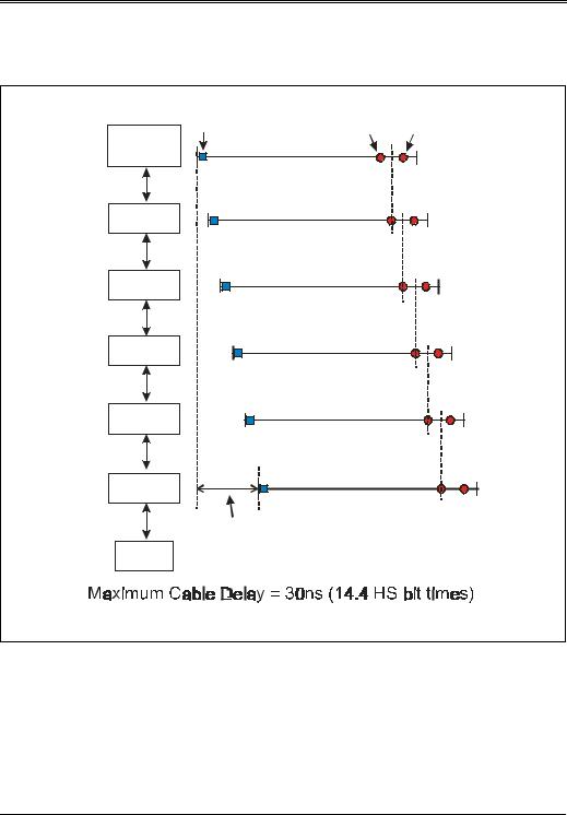
Figure 13-2 on page 269 illustrates the alignment of frame timers within the hubs. The hub timers are skewed due to the propagation delay associated with the cable and hub repeaters. This ensures that the EOF1 sample points of each downstream hub fall between the EOF1 and EOF2 sample points of the hub immediately upstream. The specification states that when any hub reaches its EOF1 sample point, it “tears down upstream connectivity.” If an upstream packet is being transferred at EOF1, then the upstream port would detect abrupt packet termination, thus ensuring that no upstream packet will be observed when the EOF2 point is reached. Note that the hub port to which the babbling device is attached will detect upstream activity from the babbling device at its EOF2 point. The hub must disable the port to prevent it from interfering with the next microframe.
Note that the proper timing relationships between the EOF points from hub to hub are critical to the detection of a babbling device. The hub designer must ensure that delays associated with SOF decoding are offset by advancing the EOF points so that the timing deltas between EOF1 points are due solely to cable and hub delays.
268
Chapter 13: HS Error Detection and Handling
Figure 13-2: Babbling Device Detection Model
Root |
SOF |
EOF1 EOF2 |
|
|
|
Hub |
|
|
Hub 1 |
|
|
Hub 2 |
|
|
Hub 3 |
|
|
Hub 4 |
|
|
Hub 5 |
|
|
|
216 HS bit times + skew |
|
Device |
|
|
Maximum Hub Delay = 36 HS bit times |
||
269

USB System Architecture
The location of the EOF1 and EOF2 sample points are specified as follows:
•EOF1 = 560 HS bit times prior to the end of microframe.
•EOF2 = 64 HS bit times prior to the end of microframe.
Figure 13-3 on page 270 illustrates the separation of the EOF sample points. The specification requires that an upstream packet that is started prior to EOF1 must reach all upstream hub ports prior to those hubs reaching their EOF2 points. This requires 216 high-speed bit times for the packet to propagate across five hubs and six cables.
Figure 13-3: Separation of EOF Sample Points
|
EOF1 |
|
|
5RRW +XE |
|
|
|
Hub 1 |
|
|
|
|
Hub 2 |
|
|
|
Hub 3 |
|
|
|
Hub 4 |
|
|
|
Hub 5 |
|
|
|
256 bit times |
240 bit times |
|
270