

What If It Doesn’t Work? • 235
What If It Doesn’t Work?
Working with motors is surprisingly easy, but a lot of things still can go wrong. The biggest problem is that motors consume a lot of power, so you cannot simply attach every motor to an Arduino. Also, you cannot easily drive more than one motor, especially not with the small amount of power you get from a USB port. If your motor doesn’t run as expected, check its specification and attach an AC or DC adapter to your Arduino if necessary.
You also shouldn’t attach too much weight to your motor. Moving an arrow made of paper is no problem, but you might run into problems if you attach bigger and heavier things. Also, be careful not to put any obstacles in the motor’s way. The motor’s shaft always needs to move freely.
Some motors have to be adjusted from time to time, and usually you have to do that with a very small screwdriver. Refer to the motor’s specifications for detailed instructions.
Exercises
•Add an Ethernet shield to the Blaminatr so you can blame people via the Internet and not only via the serial port. Pointing your web browser to an address such as http://192.168.1.42/blame/Maik should blame me.
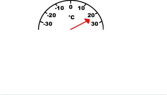
•Create a thermometer based on a TMP36 temperature sensor and a servo motor. Its display could look like the image below; that is, you have to move an arrow that points to the current temperature.
•Use an IR receiver to control the Blaminatr. You could use the channel key of your TV set’s remote control to move the Blaminatr from one name to the other.
report erratum • discuss
Part III
Appendixes

APPENDIX 1
Electronics and Soldering Basics
You didn’t need a lot of theory or background to create your first Arduino projects. But it’s a good idea to learn about electricity and about soldering if you want to build bigger and more sophisticated projects.
In this appendix, you’ll learn the basics of electricity, and you’ll learn about Ohm’s law, which is probably the most important law in electronics. Also, you’ll learn more about resistors, and you’ll see that soldering isn’t as difficult as it might seem.
Current, Voltage, and Resistance
To build your first projects with the Arduino, you didn’t need to know much about electricity. But at some point, you’ll need to understand what current, voltage, and resistance are all about. For example, you already know that you always have to put a resistor in front of an LED, but you might not know exactly why, and you might not know how to calculate the resistor’s size for a given LED. Let’s remedy that.
Electrical Circuits
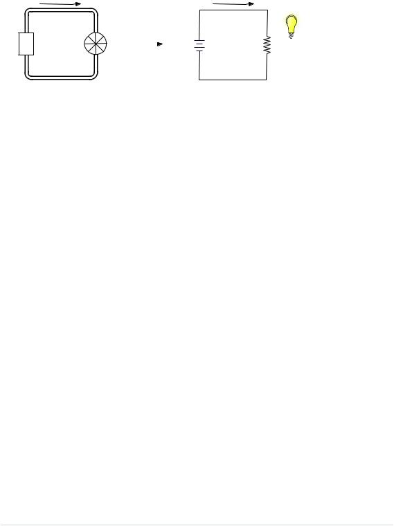
An electrical circuit resembles a water circuit in many respects. In the following figure,1 you can see a water circuit on the left and an electrical circuit on the right. Isn’t it fascinating how similar they are and that you can even find a connection between them when you use a water-driven dynamo that acts as a power supply? Let’s take a closer look at their most important attributes.
1.Lightbulb image is from Benji Park at https://openclipart.org/detail/26218/Lightbulb_Bright-by- bpcomp.
report erratum • discuss
Appendix 1. Electronics and Soldering Basics • 240
Water
Pump
Current
Water |
Dynamo |
Power |
||
Supply |
||||
|
|
|||
Mill |
|
|
Voltage |
|
|
|
|
(V) |
|
Pipe
Current (I)
+
Resistance (R)
-
Wire
While water flows in a water circuit, electrons flow in an electrical circuit. Voltage is electricity’s equivalent of water pressure and is measured in volts
(V). Voltage is the initial cause for a current, and the higher the voltage, the faster the current flows.
In electronics, current is the amount of electricity flowing through an electric line. It is the equivalent of the actual flow of water in a water circuit. While we measure the water flow in liters per minute, we measure current in amperes. One ampere means that approximately 6.24 × 10¹⁸ electrons are flowing per second.
Every component in a circuit—be it water or electricity—resists some amount of current. In a water circuit, it’s the pipes the water is flowing through or perhaps a water mill. In an electrical circuit, it is the wire or a light bulb. Resistance is an important physical phenomenon that is closely related to current and voltage. We measure it in ohms, and its official symbol is Ω.
The German physicist Georg Ohm found that current depends on voltage and resistance. He postulated the following form that we call Ohm’s law today (we use I as the current’s letter for historical reasons. In the past, it stood for inductance):
•I (current) = V (voltage) / R (resistance) This is equivalent to the following:
•R (resistance) = V (voltage) / I (current)
•V (voltage) = R (resistance) × I (current)
So, for two given values, you can calculate the third one. Ohm’s law is the only formula you’ll absolutely have to learn when learning electronics. When working with LEDs, it helps you calculate the size of the resistor you need.
If you look at an LED’s data sheet, you will usually find two values: a forward voltage and a current rating. The forward voltage usually is between 1.8V and
report erratum • discuss

Electrical Circuits • 241
3.6V, and the maximum current often is 20 mA (milliamperes). Let’s say we have an LED with a maximum of 2.5 volts and a safe current of 20 mA. We also assume that we have a power supply delivering 5 volts (as most Arduinos do). What’s the right size of the resistor we need to put in front of the LED?
We have to make sure that the resistor takes 5 – 2.5 = 2.5 volts from the circuit, so only 2.5 volts are left for the LED. This value is called voltage drop. Also, we want a maximum of 20 mA to flow through the LED. This implies that a maximum of 20 mA (0.02 A) should flow through our resistor also.
Now that we know that 2.5V and 0.02 A should pass the LED, we can use Ohm’s law to calculate the resistance R:
R = V / I
In our case, we have the following:
R = 2.5V / 0.02A = 125Ω
This means we need a 125Ω resistor for our LED. If you do not have a 125Ω resistor, use a bigger one, such as 150Ω or 220Ω. It will still protect the LED and only slightly decrease its brightness. That’s because we’d decrease the current even more:
I = 2.5V / 150Ω = 17mA
I = 2.5V / 220Ω = 11mA
Resistors
You’ll hardly ever find an electronics project that doesn’t need resistors. So, you’ll need them often and should get more familiar with them. Usually you’ll use carbon or metal resistors. Metal resistors are more precise and don’t create so much noise, but carbon resistors are cheaper. In simple circuits, it usually doesn’t matter which type you use.
The most important attribute of a resistor is its resistance value that is measured in ohms. Only a few vendors actually print this value on the resistor, because resistors are small parts, and it’s hard to read text that is small enough to fit on them. So, they use a trick and encode the value using colored stripes.
Usually you find four or five stripes on a resistor (at least on through-hole parts; SMD resistors don’t have them). One of them is separated from the others by a gap. (See the following figure.) The separate stripe is on the right side of the resistor, and it tells you about the resistor’s accuracy. Gold stands for an accuracy of ±5 percent, silver stands for ±10 percent, and no stripe
report erratum • discuss

Appendix 1. Electronics and Soldering Basics • 242
means ±20 percent. Using the remaining stripes, you can calculate the resistor value.
You read the stripes from left to right, and every color stands for a digit. (See the following figure.) The rightmost stripe—that is, the third or fourth one—stands for an amount of zeros to be added to the preceding digits. In the following figure, you can see three examples:
|
|
Color |
Code |
Zeros |
|
|
Black |
0 |
- |
|
|
Brown |
1 |
0 |
|
|
|||
|
|
Red |
2 |
00 |
|
|
|||
|
|
Orange |
3 |
000 |
|
|
|||
|
|
Yellow |
4 |
0000 |
|
|
|||
|
|
Green |
5 |
00000 |
|
|
|||
|
|
Blue |
6 |
000000 |
|
|
|||
|
|
Violet |
7 |
0000000 |
|
|
|||
|
|
Gray |
8 |
00000000 |
|
|
|||
|
|
White |
9 |
000000000 |
•On the first resistor we find four stripes: brown (1), green (5), brown (1 zero), silver (±10%). That means we have a resistor value of 150Ω.
•The second resistor has four stripes again: yellow (4), violet (7), orange (3 zeros), gold (±5%). So, this resistor has a value of 47000Ω = 47kΩ.
•The third resistor has five stripes: brown (1), red (2), red (2), green (5 zeros), silver (±10%), so the value is 12,200,000Ω = 12.2MΩ.
report erratum • discuss