

First Version of a Binary Die • 45
BinaryDice/Blink/Blink.ino
const unsigned int LED_PIN = 12; const unsigned int PAUSE = 500;
void setup() { pinMode(LED_PIN, OUTPUT);
}
void loop() { digitalWrite(LED_PIN, HIGH); delay(PAUSE); digitalWrite(LED_PIN, LOW); delay(PAUSE);
}
We’ve built a strong foundation for our project, and in the next section we’ll build upon it.
First Version of a Binary Die
You’re certainly familiar with a regular die displaying results in a range from one to six. To emulate such a die exactly with an electronic device, you’d need seven LEDs and some fairly complicated business logic. We’ll take a shortcut and display the result of a die roll in binary.
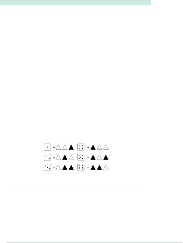
For a binary die, we need only three LEDs to represent the current result. We turn the result into a binary number, and for every bit that is set, we light up a corresponding LED. The following diagram shows how the die results are mapped to LEDs. (A black triangle stands for a shining LED.)
We already know how to control a single LED on a breadboard. Controlling three LEDs is similar and requires only more wires, LEDs, 1kΩ resistors, and pins. Figure 11, A first working version of our binary die, on page 46 shows the first working version of a binary die.
The most important difference is the common ground. When you need ground for a single LED, you can connect it to the LED directly. But we need ground for three LEDs now, so we’ll use the breadboard’s rows for the first time. Connect the row marked with a hyphen (-) to the Arduino’s ground pin, and
report erratum • discuss

Chapter 3. Building Binary Dice • 46
Figure 11—A first working version of our binary die
all sockets in this row will work as ground pins, too. Then you can connect this row’s sockets to the LEDs using short wires.
Everything else in this circuit should look familiar, because we only had to clone the basic LED circuit from the previous section three times. Note that we have connected the three LEDs to pins 10, 11, and 12. The only thing missing is some software:
BinaryDice/BinaryDice/BinaryDice.ino
Line 1 const unsigned int LED_BIT0 = 12;
-const unsigned int LED_BIT1 = 11;
-const unsigned int LED_BIT2 = 10;
-
5 void setup() {
-pinMode(LED_BIT0, OUTPUT);
-pinMode(LED_BIT1, OUTPUT);
-pinMode(LED_BIT2, OUTPUT);
-
10 randomSeed(analogRead(A0));
-long result = random(1, 7);
-output_result(result);
-}
report erratum • discuss

First Version of a Binary Die • 47
-
15 void loop() {
- }
-
-void output_result(const long result) {
-digitalWrite(LED_BIT0, result & B001); 20 digitalWrite(LED_BIT1, result & B010);
-digitalWrite(LED_BIT2, result & B100);
-}
This is all the code we need to implement the first version of a binary die. As usual, we define some constants for the output pins the LEDs are connected to. In the setup function, we set all the pins into OUTPUT mode. For the die, we need random numbers in the range from one to six. The random function returns random numbers in a specified range using a pseudorandom number generator. In line 10, we initialize the generator with some noise we read from analog input pin A0. (See Generating Random Numbers, on page 48, to learn why we have to do that.) You might wonder where the constant A0 is from. The Arduino IDE defines constants for all analog pins named A0, A1, and so on. Then we actually generate a new random number between one and six and output it using the output_result function. (The seven in the call to random is correct, because it expects the upper limit plus one.)
The function output_result takes a number and outputs its lower three bits by switching on or off our three LEDs accordingly. Here we use the & operator and binary literals. The & operator takes two numbers and combines them bitwise. When two corresponding bits are 1, the result of the & operator is 1, too. Otherwise, it is 0. The B prefix allows you to put binary numbers directly into your source code. For example, B11 is the same as 3.
You might have noticed that the loop function was left empty, and you might wonder how such a die works. It’s pretty simple: whenever you restart the Arduino, it outputs a new number, and to roll the die again, you have to press the reset button.
Compile the code, upload it to the Arduino, and play with your binary die. You have mastered your first advanced electronics project! Enjoy it for a moment!
Whenever you want to see a new result, you have to reset the Arduino. That’s probably the most pragmatic user interface you can build, and for a first prototype, this is okay. But it’s more elegant to control the dice with your own button. That’s what we’ll do in the next section.
report erratum • discuss

Chapter 3. Building Binary Dice • 48
 Generating Random Numbers
Some computing problems are surprisingly difficult, and creating good random numbers is one of them. After all, one of the most important properties of a computer is deterministic behavior. Still, we often need—at least seemingly—random behavior for a variety of purposes, ranging from games to cryptographic algorithms.
The most popular approach (used in Arduino’s random() function) is to create pseudorandom numbers.a They seem to be random, but they actually are the result of a formula. Different kinds of algorithms exist, but usually each new pseudorandom number is calculated from its predecessors. This implies that you need an initialization value to create the first random number of the sequence. This initialization value is called a random seed, and to create different sequences of pseudorandom numbers, you have to use different random seeds.
Creating pseudorandom numbers is cheap, but if you know the algorithm and the random seed, you can easily predict them. So, you shouldn’t use them for cryptographic purposes.
In the real world, you can find countless random processes, and with the Arduino, it’s easy to measure them to create real random numbers. Often it’s sufficient to read some random noise from analog pin 0 and pass it as the random seed to the randomSeed() function. You can also use this noise to create real random numbers; there is even a library for that purpose.b
If you need strong random numbers, the Arduino is a perfect device for creating them. You can find many projects that observe natural processes solely to create random numbers. One of them watches an hourglass using the Arduino.c
a.http://en.wikipedia.org/wiki/Pseudo-random_numbers
b.http://code.google.com/p/tinkerit/wiki/TrueRandom
c.http://www.circuitlake.com/usb-hourglass-sand-timer.html
Working with Buttons
In this section you’ll learn how pushbuttons work in principle and how you can use them with an Arduino. We’ll start small and build a circuit that uses a pushbutton to control a single LED.
What exactly is a pushbutton? The following figure shows three views of a typical pushbutton. It has four connectors that fit perfectly on a breadboard (at least after you have straightened them with a pair of pliers). Two opposite pins connect when the button is pushed; otherwise, they are disconnected.
report erratum • discuss

|
|
Working with Buttons • 49 |
Top |
Front |
Side |
Connected |
|
|
Connected
The following picture shows a simple circuit using a pushbutton. Connect pin 7 (chosen completely arbitrarily) to the pushbutton, and connect the pushbutton via a 10kΩ resistor to ground. Then connect the 5-volt power supply to the other pin of the button. Make sure the pushbutton’s orientation is right. Its connected pins have to bridge the gap of the breadboard.
All in all, this approach seems straightforward, but why do we need a resistor again? The problem is that we expect the pushbutton to return a default value (LOW) in case it isn’t pressed. But when the button isn’t pressed, it would be directly connected to ground and would flicker because of static and interference. Only a little bit of current flows through the resistor, and this helps prevent random fluctuations in the voltage at the input pin.
When the button is pressed, there will still be 5 volts at the Arduino’s digital pin, but when the button isn’t pressed, it will cleanly read the connection to ground. We call this a pull-down resistor; a pull-up resistor works exactly the other way around. That is, you have to connect the Arduino’s signal pin to power through the pushbutton and connect the other pin of the pushbutton to ground using a resistor.
Now that we’ve eliminated all this ugly unstable real-world behavior, we can return to the stable and comforting world of software development. The following program checks whether a pushbutton is pressed and lights an LED accordingly:
report erratum • discuss

Chapter 3. Building Binary Dice • 50
BinaryDice/SimpleButton/SimpleButton.ino
const |
unsigned |
int |
BUTTON_PIN = |
7; |
|
const |
unsigned |
int |
LED_PIN |
= |
13; |
void setup() { pinMode(LED_PIN, OUTPUT); pinMode(BUTTON_PIN, INPUT);
}
void loop() {
const int BUTTON_STATE = digitalRead(BUTTON_PIN);
if (BUTTON_STATE == HIGH) digitalWrite(LED_PIN, HIGH);
else
digitalWrite(LED_PIN, LOW);
}
We connect the button to pin 7 and the LED to pin 13 and initialize those pins in the setup function. In loop, we read the current state of the pin connected to the button. If it is HIGH, we turn the LED on. Otherwise, we turn it off.
Upload the program to the Arduino, and you’ll see that the LED is on as long as you press the button. As soon as you release the button, the LED turns off. This is pretty cool, because now we nearly have everything we need to control our die using our own button. But before we proceed, we’ll slightly enhance our example and turn the button into a real light switch.
To build a light switch, we start with the simplest possible solution. Do not change the current circuit, and upload the following program to your Arduino:
|
BinaryDice/UnreliableSwitch/UnreliableSwitch.ino |
|
Line 1 |
const unsigned int BUTTON_PIN = 7; |
|
- |
const unsigned int LED_PIN |
= 13; |
- |
|
|
- |
void setup() { |
|
5pinMode(LED_PIN, OUTPUT);
-pinMode(BUTTON_PIN, INPUT);
-}
-int led_state = LOW;
-void loop() {
10 const int CURRENT_BUTTON_STATE = digitalRead(BUTTON_PIN);
-if (CURRENT_BUTTON_STATE == HIGH) {
-if (led_state == LOW)
-led_state = HIGH;
-else
15 led_state = LOW;
-digitalWrite(LED_PIN, led_state);
-}
-}
report erratum • discuss

Working with Buttons • 51
We begin with the usual pin constants, and in setup we set the modes of the pins we use. In line 8, we define a global variable named led_state to store the current state of our LED. It will be LOW when the LED is off and HIGH otherwise. In loop, we check the button’s current state. When we press the button, its state switches to HIGH, and we toggle the content of led_state. That is, if led_state was HIGH, we set it to LOW, and vice versa. At the end, we set the physical LED’s state to our current software state accordingly.
Our solution is really simple, but unfortunately, it doesn’t work. Play around with it, and you’ll quickly notice some annoying behavior. If you press the button, the LED sometimes will turn on and then off immediately. Also, if you release it, the LED will often remain in a more or less arbitrary state; that is, sometimes it will be on and sometimes off.
The problem is that the Arduino executes the loop method over and over again. Although the Arduino’s CPU is comparatively slow, this would happen quite often—regardless of whether we are currently pressing the button. But if you press it and keep it pressed, its state will constantly be HIGH, and you’d constantly toggle the LED’s state (because this happens so fast, it seems like the LED is constantly on). When you release the button, the LED is in a more or less arbitrary state.
To improve the situation, we have to store not only the LED’s current state, but also the pushbutton’s previous state:
BinaryDice/MoreReliableSwitch/MoreReliableSwitch.ino
const |
unsigned |
int |
BUTTON_PIN = |
7; |
|
const |
unsigned |
int |
LED_PIN |
= |
13; |
void setup() { pinMode(LED_PIN, OUTPUT); pinMode(BUTTON_PIN, INPUT);
}
int old_button_state = LOW; int led_state = LOW;
void loop() {
const int CURRENT_BUTTON_STATE = digitalRead(BUTTON_PIN);
if (CURRENT_BUTTON_STATE != old_button_state && CURRENT_BUTTON_STATE == HIGH) { if (led_state == LOW)
led_state = HIGH; else
led_state = LOW; digitalWrite(LED_PIN, led_state);
}
old_button_state = CURRENT_BUTTON_STATE;
}
report erratum • discuss
Chapter 3. Building Binary Dice • 52
After initializing the button and LED pins, we declare two variables: old_button_state stores the previous state of our pushbutton, and led_state stores the LED’s current state. Both can be either HIGH or LOW.
In the loop function, we still have to read the current button state, but now we not only check whether it is HIGH, but we also check whether it has changed since the last time we read it. Only when both conditions are met do we toggle the LED’s state. So, we no longer turn the LED on and off over and over again as long as the button is pressed. At the end of our program, we have to store the button’s current state in old_button_state.
Upload the new version, and you’ll see that this solution works much better than our old one. But you will still find some cases when the button doesn’t behave fully as expected. Problems mainly occur in the moment you release the button.
These problems occur because the mechanical buttons bounce for a few milliseconds when you press them. In the following figure, you can see a typical signal produced by a mechanical button. Right after you have pressed the button, it doesn’t emit a clear signal. To overcome this effect, you have to debounce the button. It’s usually sufficient to wait a short period of time until the button’s signal stabilizes. Debouncing ensures that the input pin reacts only once to a push of the button:
Button pressed |
Button released |
5 V
0 V
In addition to debouncing, we still have to store the current state of the LED in a variable. Here’s how to do that:
BinaryDice/DebounceButton/DebounceButton.ino
Line 1 |
const |
unsigned |
int |
BUTTON_PIN = |
7; |
|
- |
const |
unsigned |
int |
LED_PIN |
= |
13; |
-void setup() {
-pinMode(LED_PIN, OUTPUT);
5pinMode(BUTTON_PIN, INPUT);
- }
-
-int old_button_state = LOW;
-int led_state = LOW;
10
- void loop() {
report erratum • discuss