


CHAPTER 5
Sensing the World Around Us
Instead of communicating via mouse or keyboard as with regular computers, you need to connect special sensors to the Arduino so that it can sense changes around it. You can attach sensors that measure the current temperature, the acceleration, or the distance to the nearest object.
Sensors make up an important part of physical computing, and the Arduino makes using various sensor types a breeze. In this chapter, we will use both digital and analog sensors to capture some real-world state, and all we need is a couple of wires and some small programs.
We’ll take a close look at two sensor types: an ultrasonic sensor that measures distances and a temperature sensor that measures, well, temperatures. With the ultrasonic sensor, we’ll build a digital metering rule to help us measure distances remotely.
Although ultrasonic sensors deliver quite accurate results, we can still improve their precision with some easy tricks. Interestingly, the temperature sensor will help us with this, and at the end of the chapter, we will have created a fairly accurate digital distance meter. We’ll also build a nice graphical application that visualizes the data we get from the sensors.
But the Arduino doesn’t only make using sensors easy. It also encourages good design for both your circuits and your software. For example, although we end up using two sensors, they are completely independent. All the programs we develop in this chapter will run without changes on the final circuit.
report erratum • discuss
Chapter 5. Sensing the World Around Us • 78
What You Need
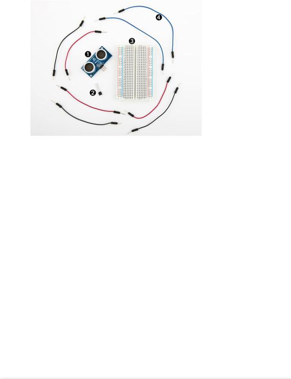
1.A Parallax PING))) sensor
2.A TMP36 temperature sensor from Analog Devices
3.A breadboard
4.Some wires
5.An Arduino board, such as the Uno, Duemilanove, or Diecimila
6.A USB cable to connect the Arduino to your computer
Measuring Distances with an Ultrasonic Sensor
Measuring distances automatically and continuously comes in handy in many situations. Think of a robot that autonomously tries to find its way or of an automatic burglar alarm that rings a bell or calls the police whenever someone is too near your house or the Mona Lisa. All this is possible with Arduino. But before you can create that burglar alarm or robot, you need to understand some key concepts.
Many different types of sensors for measuring distances are available, and the Arduino plays well with most of them. Some sensors use ultrasound, while others use infrared light or even laser. But in principle all sensors work the same way: they emit a signal, wait for the echo to return, and measure the time the whole process took. Because we know how fast sound and light travel through the air, we can then convert the measured time into a distance.
In our first project, we’ll build a device that measures the distance to the nearest object and outputs it on the serial port. For this project, we use the
report erratum • discuss
Measuring Distances with an Ultrasonic Sensor • 79
Parallax PING))) ultrasonic sensor1 because it’s easy to use, comes with excellent documentation, and has a nice feature set. It can detect objects in a range between 2 centimeters and 3 meters, and we use it directly with a breadboard, so we don’t have to solder. It’s also a perfect example of a sensor that provides information via variable-width pulses. (More on that in a few paragraphs.) With the PING))) sensor, we can easily build a sonar or a robot
|
that automatically finds its way through a maze without touching a wall. |
|
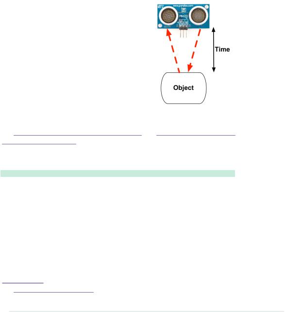
As mentioned earlier, ultrasonic sensors usually |
|
don’t return the distance to the nearest object. |
|
Instead, they return the time the sound needed |
|
to travel to the object and back to the sensor. |
|
The PING))) is no exception, and its innards are |
|
fairly complex. Fortunately, they are hidden |
|
behind three simple pins: power, ground, and |
|
signal. |
|
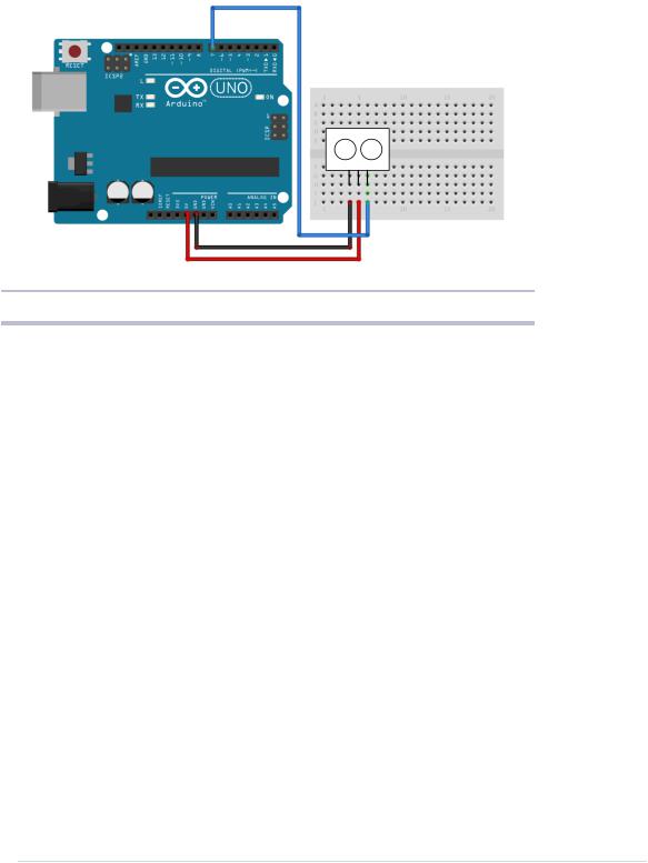
This makes it easy to connect the sensor to the |
|
Arduino. First, connect Arduino’s ground and |
|
5V power supply to the corresponding PING))) |
|
pins. Then connect the PING)))’s sensor pin to |
|
one of the Arduino’s digital IO pins. (We’re using |
|
pin 7 for no particular reason.) For a diagram and for a photo of our circuit, |
|
see Figure 15, PING))) basic circuit, on page 80 and Figure 16, Photo of PING))) |
|
basic circuit, on page 81. |
|
To bring the circuit to life, we need some code that communicates with the |
|
PING))) sensor: |
|
InputDevices/Ultrasonic/Simple/Simple.ino |
Line 1 |
const unsigned int PING_SENSOR_IO_PIN = 7; |
- |
const unsigned int BAUD_RATE = 9600; |
- |
|
- |
void setup() { |
5Serial.begin(BAUD_RATE);
- |
} |
- |
|
-void loop() {
-pinMode(PING_SENSOR_IO_PIN, OUTPUT); 10 digitalWrite(PING_SENSOR_IO_PIN, LOW);
-delayMicroseconds(2);
-
-digitalWrite(PING_SENSOR_IO_PIN, HIGH);
-delayMicroseconds(5);
1.http://www.parallax.com/product/28015
report erratum • discuss
Chapter 5. Sensing the World Around Us • 80
report erratum • discuss
Measuring Distances with an Ultrasonic Sensor • 81
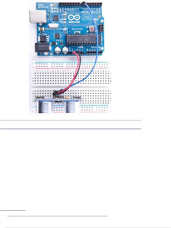
Figure 16—Photo of PING))) basic circuit
The real action happens in loop, where we actually implement the PING))) protocol. According to the data sheet,2 we can control the sensor using pulses, and it returns results as variable-width pulses, too.
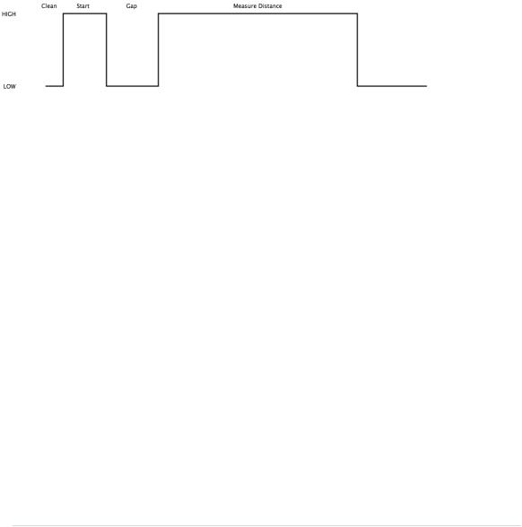
In lines 9 to 11, we set the sensor’s signal pin to LOW for 2 microseconds to bring it to a proper state. This will ensure clean HIGH pulses that are needed in the next steps. (In the world of electronics, you should always be prepared for jitters in the power supply.)
Finally, it’s time to tell the sensor to do some work. In lines 13 to 15, we set the sensor’s signal pin to HIGH for 5 microseconds to start a new measurement. Afterward, we set the pin to LOW again, because the sensor will respond with a HIGH pulse of variable length on the same pin.
2.http://www.parallax.com/downloads/ping-ultrasonic-distance-sensor-product-guide
report erratum • discuss
Chapter 5. Sensing the World Around Us • 82
With a digital pin, you have only a few options to transmit information. You can set the pin to HIGH or LOW, and you can control how long it remains in a particular state. For many purposes, this is absolutely sufficient, and in our case it is, too. When the PING))) sensor sends out its 40-kHz chirp, it sets the signal pin to HIGH and then sets it back to LOW when it receives the echo. That is, the signal pin remains in a HIGH state for exactly the time it takes the sound to travel to an object and back to the sensor. Loosely speaking, we are using a digital pin for measuring an analog signal. In the following figure, you can see a diagram showing typical activity on a digital pin connected to a PING))) sensor.
We could measure the duration the pin remains in HIGH state manually, but the pulseIn method already does all the dirty work for us. So, we use it in line 18 after we have set the signal pin into input mode again. pulseIn accepts three parameters:
•pin: Number of the pin to read the pulse from.
•type: Type of the pulse that should be read. It can be HIGH or LOW.
•timeout: Timeout measured in microseconds. If no pulse could be detected within the timeout period, pulseIn returns 0. This parameter is optional and defaults to one second.
Note that in the whole process, only one pin is used to communicate with the PING))). Sooner or later, you’ll realize that IO pins are a scarce resource on the Arduino, so it’s really a nice feature that the PING))) uses only one digital pin. When you can choose between different parts performing the same task, try to use as few pins as possible.
We have only one thing left to do: convert the duration we have measured into a length. Sound travels at 343 meters per second, which means it needs 29.155 microseconds per centimeter. So, we have to divide the duration by 29 and then by 2, because the sound has to travel the distance twice. It travels to the object and then back to the PING))) sensor. The microseconds_to_cm method performs the calculation.
report erratum • discuss
Measuring Distances with an Ultrasonic Sensor • 83
According to the specification of the PING))) sensor, you have to wait at least 200 microseconds between two measurements. For high-speed measurements, we could calculate the length of a pause more accurately by actually measuring the time the code takes. But in our case this is pointless, because all the statements that are executed during two measurements in the loop method take far more than 200 microseconds. And outputting data to the serial connection is fairly expensive. Despite this, we have added a small delay of 100 microseconds to slow down the output.
You might wonder why we use the const keyword so often. To program the Arduino you use C/C++, and in these languages it’s considered a good practice to declare constant values as const (see Effective C++: 50 Specific Ways to Improve Your Programs and Designs [Mey97]). Not only will using const make your program more concise and prevent logical errors early, but it will also help the compiler to decrease your program’s size.
Although most Arduino programs are comparatively small, software development for the Arduino is still software development, and it should be done according to all the best practices we know. So, whenever you define a constant value in your program, declare it as such (using const, not using #define). This is true for other programming languages as well, so we will use final in our Java programs, too.
Now it’s time to play around with the sensor and get familiar with its strengths and weaknesses. Compile the program, upload it to your Arduino board, and open the serial monitor (don’t forget to set the baud rate to 9600). You should see something like this:
Distance to nearest object: 42 cm
Distance to nearest object: 33 cm
Distance to nearest object: 27 cm
Distance to nearest object: 27 cm
Distance to nearest object: 29 cm
Distance to nearest object: 36 cm
In addition to the output in the terminal, you will see that the LED on the PING))) sensor is turned on whenever the sensor starts a new measurement.
Test the sensor’s capabilities by trying to detect big things or very small things. Try to detect objects from different angles, and try to detect objects that are below or above the sensor. You should also do some experiments with objects that don’t have a flat surface. Try to detect stuffed animals, and you will see that they are not detected as well as solid objects. (That’s probably why bats don’t hunt bears—they can’t see them.)
report erratum • discuss