

Schluesseltech_39 (1)
.pdf3.4 |
G. Heger |
3.3 Crystallographic coordinate systems
The description of a crystal structure consists first of the choice of a unit cell as smallest repeat unit of the crystal with its basis vectors. In this way a crystal-specific coordinate system is defined which is used to localize all the atoms in the unit cell. Whereas in physics and chemistry usually Cartesian coordinate systems are used, in crystallography quite different systems are applied. The conventional crystallographic coordinate systems are based on the symmetry of the crystals. In three dimensions there exist 7 different crystal systems and hence 7 crystallographic coordinate systems:
system name |
minimum symmetry |
conventional unit cell |
|||||||||||||||||||
|
|
|
|
|
|
|
|||||||||||||||
triclinic |
|
1 or |
|
|
|
a b c; 8 7 |
|||||||||||||||
|
1 |
|
|||||||||||||||||||
|
|
|
|
|
|
|
|
|
|
|
|
|
|
|
|
|
|
|
|
|
|
monoclinic |
one diad – 2 or m ( |
Y) |
a b c; 8=7=90°, >90° |
||||||||||||||||||
(unique axis b) |
|||||||||||||||||||||
|
|
|
|
|
|
|
|
|
|
|
|
|
|
|
|
|
|
|
|
||
|
|
|
|
|
|
|
|
|
|
|
|
||||||||||
orthorhombic |
three mutually perpendicular diads |
a b c; 8= =7=90° |
|||||||||||||||||||
– 2 or m ( |
X, Y and Z) |
||||||||||||||||||||
|
|
|
|
|
|
|
|
|
|||||||||||||
|
|
|
|
|
|
|
|
|
|
|
|
|
|
|
|
|
|
|
|
||
tetragonal |
|
|
|
|
|
|
|
|
|
|
|
Z) |
a = b |
|
c; |
8 |
7 |
||||
one tetrad |
– |
4 or 4 ( |
|||||||||||||||||||
|
|
|
= |
= =90° |
|||||||||||||||||
|
|
|
|
|
|
|
|
|
|
|
|
|
|
|
|
|
|
|
|
|
|
trigonal |
|
|
|
|
|
|
|
|
|
|
|
Z) |
a = b c; 8= =90°, 7=120° |
||||||||
one triad |
– 3 or 3 ( |
||||||||||||||||||||
(hexagonal cell) |
|||||||||||||||||||||
|
|
|
|
|
|
|
|
|
|
|
|
|
|
|
|
|
|
|
|
||
|
|
|
|
|
|
|
|
|
|
|
|
|
|
|
|
|
|
|
|
||
hexagonal |
|
|
|
|
|
|
|
|
|
|
|
Z) |
a = b |
|
c; |
8 |
|
7 |
|||
one hexad – 6 or 6 ( |
|
||||||||||||||||||||
|
|
= |
|
=90°, =120° |
|||||||||||||||||
|
|
|
|
|
|
|
|
|
|
|
|
|
|
||||||||
|
four triads |
– 3 or |
|
|
|
|
|
|
|
|
|
|
|
||||||||
cubic |
3 |
|
a = b = c; 8= =7=90° |
||||||||||||||||||
( space diagonals of cube) |
|||||||||||||||||||||
|
|
|
|
|
|
|
|
|
|||||||||||||
|
|
|
|
|
|
|
|
|
|
|
|
|
|
|
|
|
|
|
|
|
|
The choice of the origin of the coordinate system is free in principle, but for convenience it is usually chosen in a centre of symmetry (inversion centre), if present, otherwise in a point of high site symmetry of the space group.
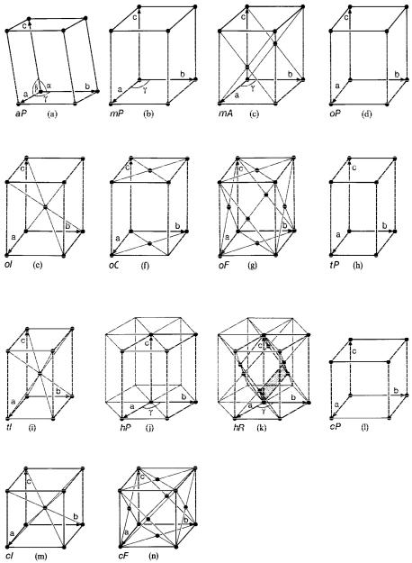
In order to complete the symmetry conventions of the coordinate systems it is necessary to add to the 7 so-called primitive unit cells of the crystal systems (primitive lattice types with only one lattice point per unit cell) 7 centred unit cells with two, three or four lattice points per unit cell (centred lattice types). These centred unit cells are consequently two, three or four times larger than the smallest repeat units of the crystals. The resulting 14 Bravais lattice types with their centring conditions are collected in figure 3.3.
Symmetry of Crystals |
3.5 |
triclinic P |
|
monoclinic P |
|
monoclinic A |
|
orthorhombic P |
|
|
monoclinic axis c |
|
(0,0,0 + 0, ½, ½) |
|
|
|
|
|
|
|
orthorhombic I |
|
orthorhombic C |
|
orthorhombic F |
|
tetragonal P |
(0,0,0 + ½, ½, ½) |
|
(0,0,0 + ½, ½,0) |
|
(0,0,0 + ½, ½,0 |
|
|
|
|
|
|
|||
|
|
|
|
½,0, ½ + 0, ½, ½) |
|
|
|
|
|
|
|
||
|
|
|
|
|
|
|
tetragonal I |
|
hexagonal P |
|
hexagonal/ |
|
cubic P |
|
|
|
|
rhombohedral R |
|
|
|
|
|
|
|
|
|
|
|
|
|
|
|
|
cubic I |
|
cubic F |
|
|
|
Fig. 3.3: The 14 Bravais lattices consisting of the 7 primitive lattices P for the 7 crystal systems with only one lattice point per unit cell + the 7 centred (multiple) lattices A, B, C, I, R and F with 2, 3 and 4 lattice points per unit cell.

3.6 |
G. Heger |
A set of lattice planes (hkl) is separated by a characteristic interplanar spacing d(hkl). According to the different crystallographic coordinate systems these d(hkl) values are calculated in a specific manner:
For the cubic lattice (a = b = c, 8 = = 7 = 90°), ex. NaCl
1
d(hkl) a h2 " k2 " l2 2
For the hexagonal lattice (a = b, c, 8 = = 90°, 7 = 120°), ex. Graphite
|
4 h |
2 |
" k |
2 |
" hk |
|
l |
2 |
|
1 |
||
|
2 |
|||||||||||
d(hkl) |
|
|
" |
|
|
|
||||||
3 |
|
|
|
a |
2 |
|
c |
2 |
|
|||
|
|
|
|
|
|
|
|
|
|
|||
For the tetragonal lattice (a = b, c, 8 = = 7 = 90°)
h2 |
" k2 |
|
l2 |
|
1 |
|||
|
2 |
|||||||
d(hkl) |
|
|
|
" |
|
|
|
|
|
a |
2 |
c |
2 |
|
|||
|
|
|
|
|
|
|||
For the orthorhombic lattice (a, b, c, 8 = = 7 = 90°)
|
2 |
|
k |
2 |
|
l |
2 |
|
1 |
|
|
|
2 |
||||||||
d(hkl) |
h |
|
" |
|
" |
|
|
|
||
|
2 |
b |
2 |
c |
2 |
|
||||
a |
|
|
|
|
|
|
|
|||
For the monoclinic lattice (a, b, c, 8 = 7 = 90°, > 90°)
(3.4)
(3.5)
(3.6)
(3.7)
|
|
|
|
|
|
|
|
|
|
|
|
|
|
h |
2 |
2 |
|
|
l |
2 |
|
|
2hlcos |
|
|
1 |
|
|
|
|
||||||||
|
|
|
|
|
|
|
|
|
|
|
|
|
|
|
|
|
|
|
|
|
||||||||||||||||||
|
|
|
|
|
|
|
|
|
|
|
|
|
|
|
|
|
2 |
|
|
|
|
|||||||||||||||||
|
|
|
|
|
|
|
|
d(hkl) |
|
|
|
|
|
" |
k |
" |
|
|
|
|
|
|
|
|
(3.8) |
|||||||||||||
|
|
|
|
|
|
|
|
2 |
|
2 |
|
2 |
2 |
2 |
|
2 |
|
|
|
|
|
|||||||||||||||||
|
|
|
|
|
|
|
|
|
|
a sin |
b |
|
c sin |
|
acsin |
|
|
|
|
|
|
|
||||||||||||||||
For the triclinic lattice (a, b, c, 8, , 7), the most general case, |
|
|
|
|
|
|
||||||||||||||||||||||||||||||||
d(hkl) |
|
cos2 cos2 cos2 " 2cos cos cos |
|
1 |
|
|
|
|
|
|
|
|
||||||||||||||||||||||||||
1 |
|
2 |
|
|
|
|
|
|
|
|
||||||||||||||||||||||||||||
|
2 |
|
|
|
2 |
|
l |
2 |
|
|
|
|
|
|
|
|
|
|
|
|
|
|
|
|
|
|
|
|
|
|
|
1 |
|
|||||
|
|
|
|
|
|
|
|
|
|
|
|
|
|
|
|
|
|
|
|
|
|
|
|
|
|
2 |
|
|||||||||||
|
h |
|
|
sin2 " |
k |
sin2 " |
|
|
sin2 |
|
|
|
|
|
|
|
|
|
|
|
|
|
|
|
|
(3.9) |
||||||||||||
|
2 |
2 |
c |
2 |
|
|
|
|
|
|
|
|
|
|
|
|
|
|
|
|||||||||||||||||||
a |
|
2kl |
|
|
|
b |
|
|
|
|
2lh |
|
|
|
|
|
|
|
|
|
|
2hk |
|
|
|
|
|
|
|
|
|
|
|
|||||
|
|
|
|
|
|
2 |
|
|
|
|
|
2 |
|
|
|
|
|
|
|
|
|
|
|
2 |
|
|
|
|||||||||||
" |
|
|
|
c cos |
|
cos " |
|
|
c cos |
7 |
cos " |
|
|
c cos 8 |
cos |
|
|
|||||||||||||||||||||
|
bc |
|
ca |
|
ab |
|
|
|||||||||||||||||||||||||||||||
|
|
|
|
|
|
|
|
|
|
|
|
|
|
|
|
|
|
|
|
|
|
|
|
|
|
|
|
|
|
|
|
|
||||||
Symmetry of Crystals |
3.7 |
3.4Crystallographic symmetry operations and symmetry elements
The symmetry operations of a crystal are isometric transformations or motions, i.e. mappings which preserve distances and, hence, also angles and volumes. An object and its transformed object superpose in a perfect manner, they are indistinguishable.
The simplest crystallographic symmetry operation is the translation, which is a parallel displacement of the crystal by a translation vector a (see chapt. 3.2). There is no fixed point, the entire lattice is shifted and therefore, theoretically, the crystal lattice is considered to be infinite.
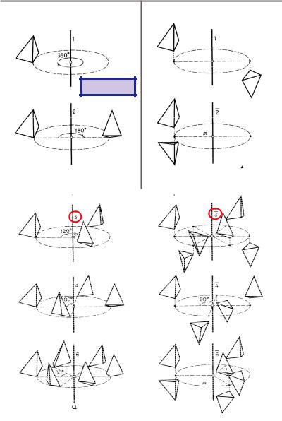
Crystallographic rotations n around an axis by an angle 9 = 360°/n (n-fold rotations) and rotoinversions (combination of rotations and inversions):n are called point symmetry operations because they leave at least one point of space invariant (at least one fixed point). An important fact of crystallographic symmetry is the restriction of the rotation angles by the three-dimensional crystal lattice to 9 = 360° (n = 1), 180° (n = 2), 120° (n = 3), 90° (n = 4), 60° (n = 6). Only for these crystallographic rotations the space can be covered completely without gaps and overlaps. The rotoinversion:n =:1 is an inversion in a point,:n =:2 m (mirror) describes a reflection across a plane.
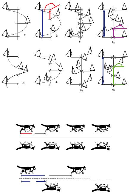
The combination of n-fold rotations with m/n a translation components (m < n) to the rotation axis leads to the so-called screw rotations nm, e.g. 21, 32, 42, 65. These symmetry operations have no fixed points.
The combination of a reflection through a plane (glide plane) with translation components (glide vectors) of a1/2, a2/2, a3/2, (a1+a2)/2, … to this plane are known as glide reflections a, b, c, n, …, d. Again no fixed points exist for these symmetry operations.
In addition to the symmetry operations which represent isometric motions of an object, symmetry can also be described in (static) geometrical terms by symmetry elements. They form the geometrical locus, oriented in space, on which a symmetry operation is performed (line for a rotation, plane for a reflection, and point for an inversion) together with a description of this operation. Symmetry elements are mirror planes, glide planes, rotation axes, screw axes, rotoinversion axes and inversion centres. The geometrical descriptions of the crystallographic symmetry operations are illustrated in Figs. 3.4-3.6.
A symmetry operation transforms a point X with coordinates x, y, z (according to a position vector X = xa1 + ya2 + za3) into a symmetrically equivalent point X’ with coordinates x’, y’, z’ mathematically by the linear equations
x’ = W11x + W12y + W13z + w1
y’ = W21x + W22y + W23z + w2 |
(3.10) |
z’ = W31x + W32y + W33z + w3
or, in matrix notation:
3.8 |
G. Heger |
Point symmetry operations
rotations
1=identity
|
|
|
|
|
|
|
|
|
|
2-fold rotation combined |
||
2-fold = 180°-rotation |
|
|
|
|
|
|||||||
|
|
|
|
with inversion = reflection |
||||||||
|
|
|
|
|
|
|
|
|
|
5 |
||
|
|
|
|
|
|
|
|
|
|
|||
|
|
|
|
|
|
1 |
|
|
||||
|
|
|
|
|
|
|
|
3 |
||||
|
|
|
|
|
|
|
|
|
|
|||
|
|
|
|
|
|
|
|
|
|
6 |
|
|
|
|
|
|
|
|
2 |
4 |
|||||
|
|
|
|
|
|
|
|
|
||||
|
|
|
|
|
|
|
|
|
|
|
|
|
|
|
|
|
|
|
|
|
|
|
|
|
|
|
|
|
|
|
|
|
|
|
|
|
|
|
|
|
|
|
|
|
|
|
|
|
|
|
|
Fig. 3.4: Rotations: n=1 (identity), n=2 (rotation angle 180°), n=3 (120°), n=4 (90°), n=6 (60°).
Rotoinversions::1 (inversion),:2 m (reflection), :3 = 3 +:1,:4,:6 = 3/m.
Symmetry of Crystals |
3.9 |
 120°
120°
1/3; 
a
a
60°
2/6;
31 = 3 + 1/3 ; |
62 = 6 + 2/6 ; |
60°
a
4/6;
+ 42, 43 and 65 |
64 = 6 + 4/6 ; |
Fig. 3.5: Screw rotations nm: combination of rotations n and translation components m/n a to the rotation axis.
a
m
reflection: mirror plane m < image plane (plane of the paper)
a 
a
a/2
glide reflection: glide plane a < with glide vector a/2
Fig. 3.6: Examples of reflections and glide reflections.

3.10 |
|
|
|
|
|
|
|
G. Heger |
x' |
W W W |
|
x |
w |
|
|
||
|
11 |
12 |
13 |
|
|
|
1 |
|
y' |
W21 |
W22 |
W23 |
|
y |
" w2 |
; X’ = W=X + w = (W, w)=X (3.11) |
|
z' |
W W W |
|
z |
w |
3 |
|
||
|
31 |
32 |
33 |
|
|
|
|
|
The (3>3) matrix W is the rotation part and the (3>1) column matrix w the translation part of the symmetry operation. The two parts W and w can be assembled into an augmented (4>4) matrix W according to
x' |
W11 |
W12 |
W13 |
||
|
|
|
|
W22 |
W23 |
y' |
W21 |
||||
z' |
W |
W |
W |
||
|
|
|
31 |
32 |
33 |
|
1 |
|
0 |
0 |
0 |
w |
1 |
|
x |
|
|
|
|
|
|
|
|
|
|
w2 |
|
y |
= W=X |
(3.12) |
||
|
|
|
|
|
||
w3 |
z |
|
|
|
||
1 |
1 |
|
|
|||
Since every symmetry transformation is a “rigid-body” motion, the determinant of all matrices W and W is det W = det W = ? 1 (+ 1: preservation of handedness; - 1: change of handedness of object).
The sequence of two symmetry operations (successive application) is given by the product of their matrices W1 and W2:
W3 = W1=W2 |
(3.13) |
whereby W3 is again a symmetry operation.
3.5 Crystallographic point groups and space groups
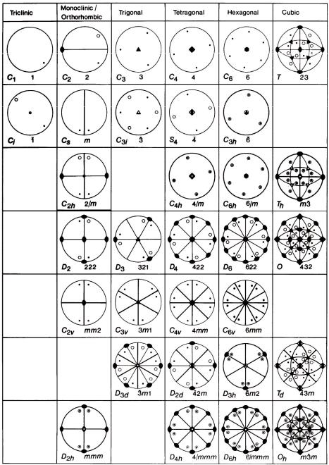
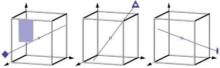
The symmetry of a crystal and of its crystal structure can be described by mathematical group theory. The symmetry operations are the group elements of a crystallographic group G and the combination of group elements is the successive execution of symmetry operations. All possible combinations of crystallographic point-symmetry operations in three-dimensional space lead to exactly 32 crystallographic point groups ( crystal classes) which all are of finite order (the maximum order is 48 for the cubic crystal class m3m ). For the different crystal systems they are represented by stereographic projections in figure 3.7. There are two types of group symbols in use: for each crystal class the corresponding Schoenflies symbol is given at the bottom left and the Hermann-Mauguin (international) symbol at the bottom right. A maximum of 3 independent main symmetry directions (“Blickrichtungen”) is sufficient to describe the complete symmetry of a crystal. These Blickrichtungen are specifically defined for the 7 crystal systems (Hermann-Mauguin symbols). As an example the Blickrichtungen of the cubic system are shown in figure 3.8.
Symmetry of Crystals |
3.11 |
Fig. 3.7: The 32 crystallographic point groups (crystal classes) in three-dimensional space represented by their stereographic projections. The group symbols are given according to Schoenflies (bottom left) and to Hermann-Mauguin (bottom right).
3.12 |
G. Heger |
z |
z |
z |
|
|
|
y |
y |
|
|
y |
||
x |
x |
x |
|
|
|
||||
[100] |
[111] |
|
[110] |
||||||
|
4 |
|
|
|
|
|
|
2 |
|
|
3 |
|
|
||||||
|
m |
|
|
m |
|||||
|
|
|
|
|
|
||||
Fig. 3.8:Symmetry directions (“Blickrichtungen”) of the cubic lattice (a=b=c, 8 790°). Along [100]: 4/m, along [111]::3, along [110]: 2/m.
The point-group symmetries determine the anisotropic (macroscopic) physical properties of crystals, i. e. mechanical, electrical, optical and thermal properties. By diffraction methods normally only the 11 centrosymmetric Laue classes can be determined:
crystal system |
Laue class |
||||||||||||||||
|
|
|
|
|
|
|
|
|
|
|
|
|
|
|
|
|
|
triclinic |
|
|
|
|
|
|
|
|
|
|
|||||||
1 |
|
|
|
|
|
|
|
||||||||||
|
|
|
|||||||||||||||
monoclinic |
1 2/m 1 = 2/m |
||||||||||||||||
|
|
|
|||||||||||||||
orthorhombic |
2/m 2/m 2/m = m m m |
||||||||||||||||
|
|
|
|
|
|
|
|
||||||||||
tetragonal |
|
|
|
|
|
4/m |
|||||||||||
4/m 2/m 2/m = 4/m m m |
|||||||||||||||||
|
|||||||||||||||||
|
|
|
|
|
|
|
|
|
|
|
|
|
|||||
|
|
|
|
|
|
|
|
|
|
|
|
|
|||||
trigonal |
3 |
|
|
|
|
|
|||||||||||
|
|
|
|
2/m = |
|
|
m |
||||||||||
|
|
|
3 |
3 |
|||||||||||||
hexagonal |
|
|
|
|
|
6/m |
|||||||||||
6/m 2/m 2/m = 6/m m m |
|||||||||||||||||
|
|||||||||||||||||
|
|
|
|
|
|
|
|
|
|
|
|
|
|
|
|
|
|
|
2/m |
|
|
= m |
|
|
|
|
|
||||||||
cubic |
3 |
3 |
|||||||||||||||
4/m |
|
|
|
2/m = m |
|
|
m |
||||||||||
|
3 |
|
3 |
||||||||||||||
Symmetry of Crystals |
3.13 |
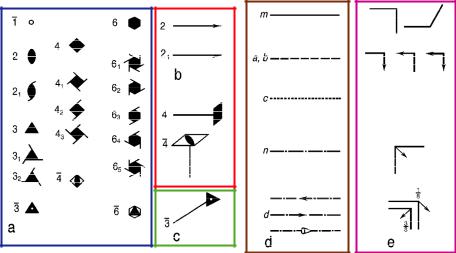
In three dimensions all possible combinations of the point symmetries of the 32 crystallographic point groups with the lattice translations of the 14 Bravais lattices lead to exactly 230 space groups, all of infinite order. As already mentioned, there result new symmetry operations: screw rotations and glide reflections. The conventional graphical symbols for the symmetry elements according to the International Tables for Crystallography Vol. A (ITA, 2002 [1]) are shown in figure 3.9.
Fig. 3.9: Conventional graphical symbols for symmetry elements:
-symmetry axes: (a) perpendicular, (b) parallel, and (c) inclined to the image plane;
-symmetry planes: (d) perpendicular and (e) parallel to the image plane.
In the International Tables for Crystallography Vol. A [1] all space groups are described in detail with their Hermann-Mauguin symbols and corresponding crystal classes, the relative locations and orientations of the symmetry elements with respect to a chosen origin and the crystal-specific basis vectors, a listing of the general and all special positions (with their symmetrically equivalent points) and the related reflection conditions.