

Schluesseltech_39 (1)
.pdf7.20 |
R. P. Hermann |
spin polarization produces an echo of the initial state. In practice, in order to avoid regions of null magnetic field where the beam could get depolarized, the neutron spins are flipped by π just before the sample and the field in the second coil is in the same direction as in the first. If elastic scattering occurs, the amplitude of the echo will not be affected; however, if some neutrons lose energy when scattered, the number of precessions before and after the scattering will be different, and the amplitude of the echo reduced. The gist of this trick is to use the spin of the neutron as an internal individual clock. The neutron spin echo technique gives the best dynamic resolution typically, 0.1μeV, and with the new JCNS instrument NSE at the SNS spallation source, measurements with time resolutions between 1 ps (0.7 meV) and 1 μs (0.7 neV) will be possible.
Appendices
APauli Spin Operators
The vector spin operator can be represented in terms of its x, y, and z components:
|
|
|
|
|
σˆ = {σˆx, σˆy, σˆz} |
|
|
|
|
|||||
where the σˆα are the Pauli matrices |
|
|
i 0 |
|
|
|
|
0 −1 |
||||||
|
x |
|
1 |
0 |
|
y |
|
|
z |
|
||||
σˆ |
|
= |
0 |
1 |
σˆ |
|
= |
|
0 −i |
|
σˆ |
|
= |
1 0 |
for a spin 1/2 particle, we can use the spin state representations |
|
|||||||||||||
|
|
|
|
|+ = |
0 |
|− = |
1 |
|
||||||
|
|
|
|
|
|
|
1 |
|
|
|
0 |
|
|
|
and accordingly, the algebra for applying the Pauli matrices to these spin states are simply given by
σˆx|+ = |− σˆy|+ = i|− σˆz|+ = |+
σˆx|− = |+ σˆy|− = −i|+ σˆz|− = −|− .
BCombined Spin and Orbital Momentum Form Factor
When the considered ions have an orbital angular momentum next to the spin angular momentum, the cross section is significantly more complicated [1]. We have to consider the total angular momentum J = L + S and we will assume weak spin-orbit interaction, e.g. the L-S or Russel-Saunders coupling, which is valid provide the atomic number is not too large. If the momentum transfer is then small, compared to the size of the Fourier transform of the electron orbits, a simplified expression is obtained in the dipole approximation
|
|
|
|
|
|
|
|
2 |
|
dσ |
= (γnr0)2 |
|
gJ |
fm(Q) |
Jˆi eiQ·Ri |
. |
(7.41) |
||
|
|||||||||
dΩmag |
2 |
||||||||
|
|
|
|
|
|
i |
|
|
|
|
|
|
|
|
|
|
|
|
|
|
|
|
|
|
|
|
|
|
|
|
|
|
|
|
|
|
|
|
|

Spin Dependent and Magnetic Scattering |
|
7.21 |
|||||
where gJ = 3 |
+ |
S(S+1)−L(L+1) |
is the Lande´ g-factor, and the form factor is |
|
|||
2 |
|
2J(J+1) |
|
|
|
||
2 |
|
|
|
fm(Q) = j0(Qr) + C2 j2(Qr) |
(7.42) |
||
|
|
|
|
|
|
||
with C2 = |
|
|
− 1 and |
|
|
|
|
gJ |
|
|
|
||||
|
|
|
|
jl(Qr) = 4π 0 |
∞ jl(Qr)R2(r)r2dr |
(7.43) |
|
where the jl(Qr) are the spherical Bessel functions and R(r) the radial density distribution. For isolated atoms, the functions j0(Q) and j2(Q) have been tabulated [18] and the R(r) have been determined by Hartree-Fock calculations.
C Scattering Cross Section for Polarized Neutrons
A full derivation of the magnetic scattering of neutrons has been obtained by Blume [5] and Maleyev [6] and accordingly the scattering process is described by two equations, one for the scattering cross-section, σ(Q) = σQ, and one for the final polarization, P :
|
|
σQ |
= σQN,coh + σisotopeN |
inc + σspinN |
inc |
|
|
|
(7.44) |
|||||||||||||
|
|
|
+ |
| |
M |
|
2 |
+ P(N |
−Q |
M + M |
N |
Q |
) |
|||||||||
|
|
|
|
|
Q| |
|
|
|
|
|
Q |
|
−Q |
|
|
|
||||||
|
|
|
+ iP(M−Q × M+Q) |
|
|
|
|
|
|
|
|
|||||||||||
P σ |
Q |
= P(σN |
|
+ σN |
|
|
) |
− |
1 PσN |
|
|
|
|
|||||||||
|
|
|
Q,coh |
|
|
isotope inc |
|
3 |
|
spin inc |
|
|
|
|
||||||||
|
|
+ MQ(PM−Q) + M−Q(PMQ) − PMQM−Q |
(7.45) |
|||||||||||||||||||
|
|
+ |
i(M |
N |
Q |
− |
M N |
−Q |
) |
× |
P |
|
|
|
|
|||||||
|
|
|
|
−Q |
|
Q |
|
|
|
|
|
|
|
|
|
|||||||
+iMQ × M−Q
+MQN−Q + M−QNQ
where NQ and MQ stands for the nuclear magnetic scattering amplitudes for a given Q.
For P = 0 only the square of the nuclear and magnetic scattering can be measured, σQ = |NQ|2 + |MQ|2 and the other terms do not contribute to the total scattering cross section. Interestingly, as indicated by the last term in Eq. 7.45, polarization can be generated in collinear structures by magnetic scattering through the interference of the nuclear and magnetic terms. For P = 0, and neglecting chiral terms, we obtain that
P = |
P σQ |
= |
MQ N−Q + M−QNQ |
(7.46) |
σQ |
|NQ|2 + |MQ|2 |
which yields P = 1 if NQ = MQ. Chiral magnetism also can lead to polarization, as indicated by the next to the last term in Eq. 7.45.
Acknowledgements
I am grateful to Th. Bruckel¨ and W. Schweika for the material in their lecture notes of the schools Neutron Scattering (2000), Chapter 3 and 4, Neutron Scattering (2008), Chapter 2 and 3, as well as Polarized Neutron Scattering (2002), material which these notes are based upon, and to W. Schweika, A. Mochel,¨ D. Bessas, and P. Zakalek for the proofreading.
7.22 |
R. P. Hermann |
References
[1]S. W. Lovesey, Theory of neutron scattering from condensed matter, Volume 2: Polarisation effects and magnetic scattering (Clarendon Press, Oxford, 1987).
[2]R. M. Moon, T. Riste , and W. C. Koehler, Phys. Rev. 181, 920-931 (1969).
[3]O. Scharpf,¨ in Neutron Spin Echo (Lectures Notes in Physics 128, Springer, 1980). See also O. Scharpf,¨ The spin of the Neutron as a measuring probe, http://82.135.31.182/neutronpol.pdf
[4]O. Halpern and M. R. Johnson, Phys. Rev. 55, 898 (1939).
[5]M. Blume, Phys. Rev. 130, 1670 (1963); Phys. Rev. 133, A1366 (1964).
[6]S. V. Maleyev, Zh. Eksperim. i Teor. Fiz. 33, 129 (1958); Zh. Eksperim. i Teor. Fiz. 33, 129 (1958). [English translation: Soviet Phys.-JETP 34, 89 (1958); Soviet Phys.-JETP 13, 860 (1961)]
[7]A. Dianoux, G. Lander (Eds.), Neutron Data Booklet (Institute Laue-Langevin, Grenoble, 2002).
[8]A. Abragam and M. Goldman, Rep. Prog. Phys. 41, 395-467 (1978).
[9]T. Chatterji and G. Schneider, Phys. Rev. B 79, 212409 (2009).
[10]A. Heidemann, Z. Phys. 238, 208 (1970).
[11]S. Disch, The Spin Structure Of Magnetic Nanoparticles And In Magnetic Nanostructures
(Schriften des Forschungszentrum Julich,¨ Key Technology Vol. 21, Julich,¨ 2011).
[12]J. Strempfer, et al., Eur. Phys. J B 14, 63 (2003); J. Strempfer, et al., Physica B 267-268, 56 (1999).
[13]Poole A., J. Phys.: Condens. Matter 19, 452201 (2007).
[14]W. Schweika, Neutron News 16, 14-17 (2005); Physica B-Cond. Matter 335, 157-163 (2003); Journal of Physics Conference Series, PNSXM 2009 211, 012025 (2009)
[15]G. Shirane, et al., Phys. Rev. B 31, 1227 (1985).
[16]O. Scharpf¨ and H. Capellmann, Phys. Stat. Sol. (a) 135, 359 (1993).
[17]J. R. Stewart, J. Appl. Cryst. 42, 69-84 (2009).
[18]E. Prince (Ed.), International Tables for Crystallography, Volume C (International Union for Crystallography, Chester CH1 2HU, England, 2004).
Spin Dependent and Magnetic Scattering |
7.23 |
Exercises
Exercises marked with * have priority, others are optional.
E7.1 Coherent and incoherent scattering cross section*
The values for coherent and incoherent neutron scattering length and cross section are tabulated in several references. An excerpt from the ILL Neutron Data Booklet [7] is given below for several elements and isotopes. Fill in the missing values indicate by XX in the table below (optional: YY).
Table 7.1: Selected scattering lengths and cross-sections. p: abundance in %; bc,+,−: bound coherent, spin dependent I+1/2 and I-1/2 scattering lengths, respectively, in fm; σcoh,inc,abs : coherent, incoherent, and absorption (at 25.3 meV) cross-section in barn.
Z |
SymbA |
p |
I |
b |
c |
b |
+ |
b |
− |
σ |
coh |
σ |
inc |
σ |
abs |
|
|
|
|
|
|
|
|
|
|||||||
1H |
|
|
-3.7409(11) |
|
|
|
|
1.7568(10) |
XX |
0.3326(7) |
|||||
1H1 |
99.885 |
1/2 |
-3.7423(12) 10.817(5) -47.420(14) |
XX |
XX |
0.3326(7) |
|||||||||
1H2 |
0.0149 |
1 |
6.674(6) |
9.53(3) |
0.975(60) |
XX |
2.05(3) |
0.000519(7) |
|||||||
21Ti |
|
|
-3.370(13) |
|
|
|
|
1.485(2) |
2.87(3) |
6.09(13) |
|||||
25Mn55 |
100 |
5/2 |
-3.750(18) |
-4.93(46) |
-1.46(33) |
YY |
XX |
13.3(2) |
|||||||
27Co59 |
100 |
7/2 |
XX |
-9.21(10) |
3.58(10) |
XX |
XX |
37.18(6) |
|||||||
28Ni |
|
|
XX |
|
|
|
|
13.3(3) |
XX |
YY |
|||||
28Ni58 |
67.88 |
0 |
14.4(1) |
|
|
|
|
26.1(4) |
|
0 |
4.6(3) |
||||
28Ni60 |
26.23 |
0 |
2.8(1) |
|
|
|
|
0.99(7) |
|
0 |
2.9(2) |
||||
28Ni61 |
1.19 |
3/2 |
7.60(6) |
YY |
YY |
7.26(11) |
1.9(3) |
2.5(8) |
|||||||
28Ni62 |
3.66 |
0 |
-8.7(2) |
|
|
|
|
9.5(4) |
|
0 |
14.5(3) |
||||
28Ni64 |
1.08 |
0 |
-0.37(7) |
|
|
|
|
0.017(7) |
|
0 |
1.52(3) |
||||
40Zr |
|
|
7.16(3) |
|
|
|
|
6.44(5) |
0.02(15) |
0.185(3) |
|||||
E7.2 Neutron contrast*
The scattering length averaged over all Zr and Ti isotopes are given in Table 7.1. Zr1−xTix alloys, with a hexagonal crystalline structure can be prepared for continuous values of x. Which x would you choose if you had to construct a sample chamber from such an an alloy? Why? What would be the disadvantage?
E7.3 Precession*
A fully polarized beam of cold neutrons with a wavelength of 5.4 A˚ enters the primary coil of a spin echo spectrometer. The coil have a length of 2.2 m, and the 1000 Oe field inside the coil is along the horizontal flight path. The initial direction of the neutron spins is in the vertical direction. What is the direction of the neutron spins at the exit of the coil? Spin echo spectrometers typically work with a 10 % or 20 % bandwidth in λ/λ. What polarization of the neutron beam do you expect at the exit of the coil considering the full bandwidth?
7.24 |
R. P. Hermann |
|
|
|
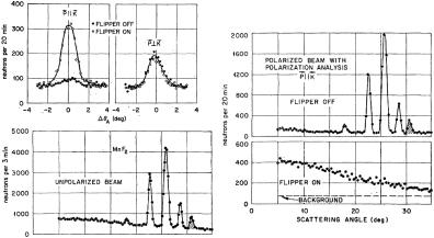
Fig. 7.13: Polarization analysis of the scattering by MnF2. Note that K stands for Q [Source: Ref. [2]].
E7.4 Flipping**
A Mezei coil with 1 cm total thickness is used as a spin flipper. The field inside the coil is perpendicular to both the polarization of the beam and the travel direction of the neutron. What field would you chose for carrying out a π-flip of the neutron polarization, considering a monochromatic beam with λ=3.4 A?˚ Is this solution unique? If not, what solution would you choose for a neutron bandwidth of 5 %?
E7.5 Flipping ratio and corrections*
Using an ideal Zr1−xTix alloy scatterer with purely isotopic incoherent scattering, the spinflip and non-spin-flip intensities, ISF = 1000 and INSF = 19000 counts, respectively, were determined at Q = 2 A˚ −1 (the background is subtracted). What is the flipping ratio and what is the polarization of the neutron beam? What flipping ratio would you obtain using a purely spin incoherent scatterer (such as, in good approximation, vanadium)? Is it preferable to determine the flipping ratio with V or with Zr1−xTix? Why?
E7.6 Magnetic scattering***
Determine the relative spin-incoherent, spin-coherent, and magnetic scattering by MnF2 from the data in Fig. 7.13a . How do you interpret Fig. 7.13d: a) what type of scattering is seen? b) why does this scattering decrease with increasing angle? c) what information could you extract from this data?
8Structural Analysis
G. Roth
Institute of Crystallography
RWTH Aachen University
Contents
8.1 |
Introduction....................................................................................... |
2 |
8.2 |
Diffraction Contrast Variation ........................................................ |
2 |
8.3 The hydrogen problem in structural analysis ................................ |
4 |
|
8.4 Atomic coordinates and displacement parameters........................ |
7 |
|
8.5 Magnetic structures from neutron diffraction............................... |
9 |
|
8.6 Electron densities from x-rays and neutrons................................ |
11 |
|
8.7 Magnetization densities from neutron diffraction....................... |
13 |
|
References .................................................................................................. |
14 |
|
Exercises..................................................................................................... |
15 |
|
________________________
Lecture Notes of the JCNS Laboratory Course Neutron Scattering (Forschungszentrum Jülich, 2011, all rights reserved)
8.2 |
G. Roth |
8.1 Introduction
The analysis of crystal structures and magnetic ordering is usually based on diffraction phenomena caused by the interaction of matter with x-rays, neutrons or electrons. Even though modern electron microscopy (HRTEM) can achieve atomic resolution, more detailed and quantitative information on the 3D atomic arrangement in crystals and on 3D magnetic structures and spin densities requires diffraction methods. In a more general nomenclature, diffraction is equivalent to coherent, elastic scattering. The basic theory of diffraction used for structural analysis (the so called kinematical theory) is similar for all types of radiation. Due to the different properties of x-rays, neutrons and electrons and their specific interaction with matter, complementary information is obtained from experiments with different types of radiation.
Considering only x-rays and thermal neutrons one finds that their wavelengths are similar (0.5 Å < B < 2.4 Å) but they are scattered very differently by matter: While the electromagnetic x-radiation is scattered from the electrons and yields the total electron density distribution in the crystal, the nuclear scattering of neutrons is sensitive to the density distribution of the nuclei and the magnetic neutron scattering probes the magnetisation density of unpaired electrons.
x-ray diffraction using conventional laboratory equipment and/or synchrotron installations is the most frequently used method for structure analysis. Neutrons are, however, indispensable in a number of applications. The purpose of this chapter is to discuss a few typical examples of structural analysis, for which, instead of or complementary to x-rays, neutrons are required to solve structural problems.
8.2 Diffraction Contrast Variation
A great advantage of neutrons over x-rays in the context of structural analysis is the very much different variation of the scattering length of atoms within the periodic system of the elements: The contrast in conventional x-ray diffraction is directly related to the ratio of the number of electrons Zj of the different atoms or ions j involved. The atomic scattering factor fj in the structure-factor formula, which represents the Fourier transform of the atomic electron density distribution, is proportional to Zj (fj = Zj for sin JB = 0). Standard x-ray techniques can hardly differentiate between atoms/ions with a similar number of electrons (like Si and Al or Cr and Mn). Even if the atoms are fully ordered on different sites, x-ray diffraction just ‘sees’ the average structure.
For neutrons the atomic scattering factor fj is replaced by the nuclear scattering length (or coherent scattering amplitude) bj, which is of the same order of magnitude for all nuclei but varies from nucleus to nucleus in a non-systematic way. bj values can be either positive or negative and depend on the isotopes and nuclear spin states of the element j (see chapter 4).
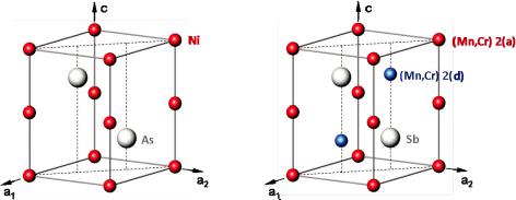
Crystal structure and site occupation of (Mn1-xCrx)1+4Sb.
As an example of contrast variation, the combination of x-ray and neutron diffraction information is demonstrated for the intermetallic compounds (Mn1-xCrx)1+4Sb, with
Structural Analysis |
8.3 |
05K5x K 1 [1]. This solid solution system is interesting for its magnetic properties: One end member of the solid solution series (Mn1+4Sb) shows isotropic ferromagnetic behaviour while the other one (Cr1+4Sb) is a uniaxial antiferromagnet. Intermediate compositions are characterized by competing magnetic interactions leading to a complex magnetic phase diagram. The crystal structure is closely related to the hexagonal NiAs-type structure (space group: P63/mmc) with some additional partial occupation (K5TU14) of the interstitial site 2(d) (see Fig. 8.1):
Fig. 8.1: Left: NiAs structure, right: (Mn1-xCrx)1+4Sb structure
Conventional x-ray diffraction can hardly differentiate between chromium (ZCr= 24) and manganese (ZMn= 25) but still yields information on the overall occupation probabilities by (Mn,Cr) for site 2(a) (denoted as a) and site 2(d) (denoted as d). The Sb position is assumed to be fully occupied, thus serving as an internal standard for the scattering power.
The compound formula can now be reformulated site-specifically as:
(Mn1-y Cry)a (Mn1-z Crz)d Sb
site 2(a) |
site 2(d) |
corresponding to a chemical composition of Mn[(1-y)a + (1-z)d] Cr[ya +zd] Sb.
On the other hand, the nuclear scattering lengths of Cr and Mn for neutron diffraction are extremely different with bCr = +3.52 fm and bMn = -3.73 fm (see also chapter 4).
In the structure analysis of the neutron data, site-specific effective scattering lengths beff (2a) and beff (2d) are refined, which in turn are expressed as:
beff(2a) = a·[(1-y)·bMn + y·bCr] and beff(2d) = d·[(1-z)·bMn + z·bCr]
solving for the unknown parameters y and z gives:
y = [beff(2a)/a - bMn] / [bCr - bMn] and z = [beff(2d)/d - bMn] / [bCr - bMn].
The combination of the overall occupation probabilities a and d - from conventional x- ray studies – with the effective scattering lengths beff(2a) and beff(2d) determined in a neutron diffraction experiment allows the evaluation of the Cr and Mn concentrations on the different sites 2(a) and 2(d).
8.4 |
G. Roth |
It is evident, that the individual (Cr,Mn) distributions on the two crystallographically different sites 2(a) and 2(d) are not accessible merely by a chemical analysis. For most of the samples studied, the site 2(a) was found to be fully occupied: a 1.0. But the formula (Mn1-xCrx)1+4Sb used normally is only correct for the special case of equal Cr : Mn ratios on both sites:
x = y = z and 1 + 4 = a + d.
Note that, in general, a statistical occupation of one crystallographic site with three kinds of scatterers - e.g. Mn, Cr and "vacancies" - requires at least two independent experiments with sufficiently different relative scattering power of the atoms involved to determine the fractional occupancies.
The detailed information on the (Cr,Mn) distribution is needed to explain the magnetic properties of these intermetallic compounds, but we will not further elaborate on this.
8.3 The hydrogen problem in structural analysis
The determination of the structural parameters (coordinates, displacement parameters) of hydrogen atoms in crystals is a special problem involving again the different properties of x-rays and neutrons. It is obvious that H or D atoms with Z = 1 give only a small contribution to the electron density and, therefore, they are hardly visible in x-ray structure analysis, particularly if heavy atoms are also present in the structure. However, there is an even more fundamental problem: The single electron of H or D is engaged in the chemical bonding and is by no means localised at the proton/deuteron position. Therefore, bond distances from x-ray diffraction involving hydrogen are notoriously wrong and any comparison with quantum mechanical calculations is quite hard to perform. This lack of sound experimental information is in sharp contrast to the importance of hydrogen bonding in solids, particularly in biological molecules like proteins, where hydrogen bonds govern to a large extent structures and functionalities of these ‘bio-catalysts’. A combination with neutron diffraction experiments is important to determine the structural parameters of the H/D atoms properly. More generally, the structure analysis by neutron diffraction yields separately and independently from the x- ray data the structure parameters of all atoms including the mean square displacements due to static and dynamic (even anharmonic) effects.
H/D ordering in ferroelectric RbH2PO4 (RDP):
The hydrogen problem in crystal structure analysis is of special importance for structural phase transitions driven by proton ordering. KH2PO4 (KDP) is the most wellknown representative of hydrogen-bonded ferroelectrics. Here, we discuss the isotypic RbH2PO4 (RDP). The crystal structure consists of a three-dimensional network of PO4- groups linked by strong hydrogen bonds (Fig. 8.2).
Structural Analysis |
8.5 |
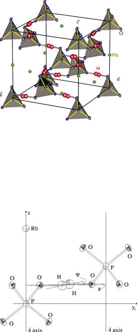
Fig. 8.2: Crystal structure of the paraelectric phase of RDP (RbH2PO4) with a splitmodel representation of the hydrogen disorder [3].
In the paraelectric phase at room temperature KDP as well as RDP crystallise in the tetragonal space group I:42d, where the H-atoms are dynamically disordered in symmetric O···H···O bonds, which are almost linear with short O–O distances, typically in the range of 2.5 Å. The disordered H-distribution may be interpreted as corresponding to a double-well potential [2].
Figures 8.3 and 8.4 show the corresponding results for RDP, obtained from single crystal neutron diffraction [3].
Fig. 8.3: Local configuration of two PO4-tetrahedra in the paraelectric phase of RDP (RbH2PO4)(at Tc + 4 K) linked by a strong, disordered hydrogen bond [3].