

Schluesseltech_39 (1)
.pdf7.10 |
R. P. Hermann |
Fig. 7.5: The form factor of Cr metal for nuclear, spin moment, and orbital moment neutron scattering, and for x-ray charge scattering, adapted from Ref. [12] and of Mn2+ ions in MnF2 adapted from Ref. [2]. Curves and points indicate theory and experiment, respectively.
scattering process, and by decomposing M (Q) in its components we obtain
A(Q) = |
|
γnr0 |
|
|
|
− |
M |
|
Q,z |
|
|
|
|
|
|
|
|
|
|
|
|||
|
− 2μB |
· |
M |
M Q,z |
Q,y |
||||||
|
Q,x |
|
iM |
||||||||
|
|
|
|
|
|
|
|
|
|
|
|
|
|
|
|
|
|
|
|
− |
|
|
|
|
|
|
|
M Q,x + iM Q,y |
|||||||
|
|
|
|
|
|
|
|
|
|
|
|
|
|
|
|
|
|
|
|
|
|
|
|
|
|
|
|
|
|
|
|
|
|
|
|
for the ++ NSF case,
for the -- NSF case,
(7.25)
for the +- SF case, for the -+ SF case.
Note that exactly as for spin incoherent scattering, a flip of the neutron spin occurs only if there is a component of M Q which is not parallel to the neutron spin. Again, as will be discussed later, this can be exploited in order to separate magnetic scattering experimentally. A simple, interesting, and important case is achieved when the neutron spin is parallel to the scattering vector: in this case M Q is always perpendicular to the spin, and thus all magnetic scattering will involve a spin flip.
The total scattering amplitude A(Q) thus consist of two parts, the nuclear and the magnetic scattering and can be simply written as
A(Q) = N(Q) + σˆ · M (Q) |
(7.26) |
where N(Q) is the nuclear scattering amplitude and contains the nuclear coherent, the isotope incoherent, and the spin incoherent part. The derivation of the resulting scattering cross sections in the general case of a polarized neutron beam is given in Appendix C.
A final question concerns the spin-flip process, and again, in such a process angular momentum is exchanged and potentially there is also an exchange in energy. In ordered magnetic materials,
whenever the neutron undergoes a spin-flip, |
S = 1, there must also be a change in the |
total electronic angular momentum, J, given by |
J = ±1, which typically creates a magnetic |
excitation, a so called magnon. Inelastic magnetic scattering can thus be used in order to map out the spectrum of magnetic excitations. In paramagnets a similar process is possible, but the excitations are not well defined in energy and the spectrum is strongly broadened out. Generally
Spin Dependent and Magnetic Scattering |
7.11 |
speaking, inelastic magnetic scattering will reveal any magnetic fluctuation perpendicular to the scattering vector.
7.4Polarization and Separation Rules
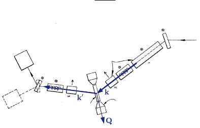
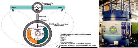
We have seen in the two previous sections that both spin incoherent and magnetic scattering can lead specifically to a flip of the neutron spin upon scattering. It is possible to take advantage of this specificity if this spin flip process can be experimentally measured. In order to do so, devices are required to detect and manipulate the neutron spin. For a schematic instrument, this is solved by measuring the polarization of the neutrons scattered by the sample impinged upon by an initially polarized neutron beam. An example of such instrument is given in Fig. 7.6.
The polarization of a neutron beam, P, is defined by the expectation value of the neutron spin
operator, ˆ,
S
ˆ |
(7.27) |
P = 2S . |
An equivalent alternative definition is that the polarization, P , with respect to the quantization axis is given by the number of neutrons with spin up and down states, n↑ and n↓, respectively, as
(7.28)
|
|
|
|
|
|
|
|
|
|
|
|
|
|
|
|
|
|
|
|
|
|
|
Fig. 7.6: Schematic setup for a triple axis polarized neutron scattering experiment with polarization analysis. The field generated by the electromagnet could be used to align a sample either in a horizontal or vertical magnetic field (Adapted from Ref. [2]).
In order to experimentally realize a polarized neutron beam a polarizing device is required, as the neutrons extracted from the moderator, see Chapter 2.3, are initially unpolarized, e.g. P = 0. In analogy with optics, there are two important ways to polarize the beam; either the neutrons with the ’wrong’ polarization are absorbed, or these neutrons are separated and directed to another direction. In practice, there are three types of polarizing devices:
7.12 |
R. P. Hermann |
a)filters that absorb the neutrons in one of the spin states and transmit the others. In practice this can be realized with polarized 3He gas cells, where the nuclear spins are kept aligned. The absorption cross section is very large for neutrons with the spin anti-parallel to the nuclear spin, and thus only the neutrons with the spin parallel to the 3He nuclear spins are transmitted.
b)super-mirrors, which show total reflection for one spin state only. These mirrors are realized as magnetic layered structures, see Chapters 9 and 10.
c)Bragg scattering from a crystal monochromator, e.g. Heusler alloy crystals, where a reflection is chosen such that the magnetic and nuclear scattering interfere destructively for one spin state and constructively for the other, see Appendix C.
When constructing a neutron scattering instrument, the choice of the polarizer will depend on the specific design. Bragg scattering monochromators reach excellent polarization but often transport only a small wavelength band and divergence of the neutron beam. Super mirrors achieve excellent polarization in a wider band but perform best only for long wavelength, i.e. cold neutrons. 3He filters perform very well for thermal neutrons and their efficiency is tunable by adjusting the pressure in the cell. At the end of the day, however, a compromise must always be found between the degree of polarization that is required and the intensity of the neutron beam. As will be discussed below, it is not necessary to have a perfect polarization, as corrections can be made to account for P < 1.
Having now achieved the polarization process, the beam must be transported to the sample while preserving the polarization. In principle, establishing a zero field region by screening any magnetic field disturbance would work, see Fig. 7.9, but in practice, it is customary to use a magnetic guide field, the field being parallel or antiparallel to P. The field should be fairly homogeneous in order to avoid precession with unwanted angular components. Such guide fields are typically weak enough not to modify the sample magnetization, but strong enough, typically 1 mT, to avoid adverse effects from the earth magnetic field or other stray fields. Depending on whether the polarizer is located far or near from the sample, one would use polarized neutron guides, adding to the cost of the instrument, or simple guide fields generated by magnetic coils. The advantage of the former is that the neutrons with the wrong polarization are absorbed far from the sample and do not contribute to neutron and radiation background.
In order to manipulate the direction of the polarization, as required for measuring polarization components in different directions, variations of the guide field can be used. If the field changes slowly, the neutrons, moving with a velocity
˚ |
(7.29) |
v(λ) = 3956 m/s · A/λ, |
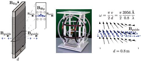
will keep their precession motion along a magnetic field that varies slowly in space. This slow precession should be smaller than the Larmor precession in the guide field. The slow field change is used to align the polarization in a particular direction at the sample position. If the field changes rapidly, the polarization does not follow and the neutrons will start to precess in the new field. A specific case of interest is when two guide fields have opposite directions, as can be achieved by separating the fields by strong currents in a metallic sheet. The polarization that was originally parallel to the first guide field would then end up antiparallel to the second guide field.
An alternative way for modifying the direction of the polarization is the use of flippers, see Fig. 7.7. The neutrons will start to precess immediately if they are subject to a field (or a field com-
Spin Dependent and Magnetic Scattering |
7.13 |
|||||||||||||||||||||||||||
|
|
|
|
|
|
|
|
|
|
|
|
|
|
|
|
|
|
|
|
|
|
|
|
|
|
|
|
|
|
|
|
|
|
|
|
|
|
|
|
|
|
|
|
|
|
|
|
|
|
|
|
|
|
|
|
|
|
|
|
|
|
|
|
|
|
|
|
|
|
|
|
|
|
|
|
|
|
|
|
|
|
|
|
|
|
|
|
|
|
|
|
|
|
|
|
|
|
|
|
|
|
|
|
|
|
|
|
|
|
|
|
|
|
|
|
|
|
|
|
|
|
|
|
|
|
|
|
|
|
|
|
|
|
|
|
|
|
|
|
|
|
|
|
|
|
|
|
|
|
|
|
|
|
|
|
|
|
|
|
|
|
|
|
|
|
|
|
|
|
|
|
|
|
|
|
|
|
|
|
|
|
|
|
|
|
|
|
|
|
|
|
|
|
|
|
|
|
|
|
|
|
|
|
|
|
|
|
|
|
|
|
|
|
|
|
|
|
|
|
|
|
|
|
|
|
|
|
|
|
|
|
|
|
|
|
|
|
|
|
|
|
|
|
|
|
|
|
|
|
|
|
|
|
|
|
|
|
|
|
|
|
|
|
|
|
|
|
|
|
|
|
|
|
|
|
|
|
|
|
|
|
|
|
|
|
|
|
|
|
|
|
|
|
|
|
|
|
|
|
|
|
|
|
|
|
|
|
|
|
|
|
|
|
|
|
|
|
|
|
|
|
|
|
|
|
|
|
|
|
|
|
|
|
|
|
|
|
|
|
|
|
|
|
|
|
|
|
|
|
|
|
|
|
|
|
|
|
|
|
|
|
|
|
|
|
|
|
|
|
|
|
|
|
|
|
|
|
|
|
|
|
|
|
|
|
|
|
|
|
|
|
|
|
|
|
|
|
|
|
|
|
|
|
|
|
|
|
|
|
|
|
|
|
|
|
|
|
|
|
|
|
|
|
|
|
|
|
|
|
|
|
|
|
|
|
|
|
|
|
|
|
|
|
|
|
|
|
|
|
|
|
|
|
|
|
|
|
|
|
|
|
|
|
|
|
|
|
|
|
|
|
|
|
|
|
|
|
|
|
|
|
|
|
|
|
|
|
|
|
|
|
|
|
|
|
|
|
|
Fig. 7.7: (a) A neutron spin flipper. Wires are typically Al in order to minimize absorption. Adapted from Ref. [3]. (b) A set of xyz Helmholtz coils used for adiabatically guiding the neutron polarization in an arbitrary direction at the sample position [Source: http://www.serviciencia.es]. (c) Neutrons adiabatically follow a field which rotates by π/2. B must be sufficient strong so that ω ωL [3].
ponent) perpendicular to their polarization. By defining a region in space where the neutrons are subject to a perpendicular field, it is thus possible to have them precess by a defined angle. One can, for example, use a long rectangular coil, with thickness d to make a homogeneous field, H = n · I where n is the linear wire density and I the current, parallel to the coil axis and perpendicular to the neutron polarization. During the time the neutrons spend in the coil, t = d/v, they precess around this field. A rotation of 180◦ or π radian is realized when
ω · t = −γB · d/v = π. |
(7.30) |
Accordingly for such a π-flipper, by combining Eqs. 7.13, 7.29, and 7.30,
|
π |
˚ |
|
67.83 |
˚ |
|
B = |
|
( m/s · A/λ)/(2916 |
· 2π Hz/Oe) = |
|
cm A Oe. |
(7.31) |
d |
dλ |
For a 1 cm coil and a wavelength of 2.2 A,˚ a field of 30 Oe or 3 mT is thus required for a rotation of 180◦. It is crucial to note that for a given width of the coil and a given field the π-flip is perfect only for one particular wavelength, i.e. for a monochromatic beam. Using the same approach, it is also possible to generate a π/2-flip. After such a flipper the polarization will be perpendicular to the guide field, and thus precess in a plane perpendicular to the guide field. Such precession mode can be use for example in spin echo spectrometers, see Fig. 7.12. Spin flippers can also be build by using radio frequency resonators, where the time dependence of the fields is the control parameter.
A final element in our schematic instrument is the detector for the polarization of the neutron beam. Again in analogy to optics, this is easily solved by combining a polarizer, which we simply call analyzer as it comes second, with a general (unpolarized) detector. Possible physical realizations are a Heusler alloy crystal that both selects a polarization and deflect the beam towards the detector, see Fig. 7.6, a 3He cell placed in front of the detector, or a set of supermirrors that only transmits a given polarization, as in Figs. 7.10 and 7.11.
7.14 |
R. P. Hermann |
We now need to link what we have learned about the scattering cross sections with what is
measured in an experiment. The experimentally accessible quantities are the intensities dσ NSF
dΩ x,y,z
and dσ SF , which can be obtained e.g. by using a beam polarized in z direction, passing through
dΩ x,y,z
a π-flipper that can be on or off, then having a guide field (slowly) bring the polarization in either x, y, or z direction at the sample and back to the z direction after the scattering, and finally measuring the intensity after an analyzer.
For soft matter investigations or when there is no magnetism, two measurements are sufficient: NSF and SF in one direction. For colinear magnetism, three measurements at least are required, but often six are done for completeness (SF and NSF in x,y, and z). In the most general case more terms, up to 18, that involve mixing the initial and final polarization directions can be obtained (e.g. from z to y), for example by using zero field sample environment [13] or a spin precession technique [14].
Having established a workable idealized instrument, that allows one to measure the polarization of the scattered neutrons, we can use the relations Eqs. 7.10 and 7.25 in order to experimentally separate the different contributions and thus measure the spin incoherent, the coherent (i.e. isotopically incoherent and nuclear coherent), and the magnetic scattering.
For the spin incoherent scattering, the expectation values and squared expectation values of Ix, Iy, and Iz are relevant. The nuclear spin orientation is in general random, with two notable exceptions, namely (dynamic) nuclear polarization [8] at low temperature and polarized 3He cells, exceptions that we will neglect in what follows. Accordingly, the expectation values for stochastic nuclear spin orientation are
|
Ix = Iy = Iz = 0, |
(7.32) |
||
and for the square operators: |
|
|
|
|
Ix2 |
= Iy2 = Iz2 = |
1 |
I(I + 1) . |
(7.33) |
|
||||
3 |
||||
By considering separately the case for the z, x, and y nuclear spin orientations, and then summing up the x and y cases that give rise to spin flip scattering, we obtain that
dσ NSF |
1 |
2 |
dσ SF |
|
2 |
2 |
(7.34) |
|||
|
|
= 3 NB I(I + 1) , |
|
|
= |
3 NB I(I + 1) . |
||||
dΩspin inco |
dΩspin inco |
|||||||||
|
||||||||||
First, we consider the case when there is no magnetic scattering involved, i.e isotropic scatter-
ing from the point of view of polarization. The measurement of |
dσ NSF |
and |
dσ SF |
is sufficient |
dΩ z |
dΩ z |
(consider that the background has been subtracted). The NSF differential cross section corresponds to the coherent scattering plus one third of the spin incoherent scattering, whereas the SF differential cross section corresponds to two thirds of the spin incoherent scattering, see Eqs. 7.10 and 7.34. The different contributions can thus be obtained by
dσ |
|
|
|
3 dσ SF |
|
||||||||
|
|
= |
|
|
|
|
|
, |
|
|
|
||
|
|
|
|
|
|
|
|||||||
dΩspin inco |
2 dΩ |
1 dσ SF |
(7.35) |
||||||||||
dσ |
|
dσ NSF |
|
||||||||||
|
|
= |
|
|
|
|
− |
|
|
|
. |
|
|
dΩcoh |
dΩ |
|
|
2 |
dΩ |
|
|||||||
Spin Dependent and Magnetic Scattering |
7.15 |
Second, considering now the possibility for magnetic scattering, it is required to distinguish the cases where the magnetization is perpendicular and parallel to the scattering vector. We will chose the coordinates such that the scattering vector is in a horizontal plane and in the x direction, and the z direction is vertical. Obviously, according to Eq. 7.17, the component of the sample magnetization parallel to the scattering vector will not contribute to the scattering, that is, in this case Mx is not accessible. As further simplification we will consider that if the material is ferromagnetic, a sufficiently strong field is applied in order to saturate the moments and to remove domain boundaries that would depolarize the beam, and we neglect possible magnetic chirality.
A first method to determine the magnetic scattering is the so-called - method. Consider the spin-flip and non spin-flip intensities for the two cases where the polarization (or the applied guide field) is first parallel to Q, i.e in x direction and parallel to M (Q), and second perpendicular to Q and in z direction. The scattering intensities are then
|
Polarization/Field |
Spin-flip |
|
|
|
|
|
|
|
|
Non spin-flip |
|
|
|
|||||||||
|
|
2 dσ |
|
|
|
|
dσ |
M |
dσ |
M |
|
|
dσ |
|
|
1 dσ |
|
|
|
||||
|
P x Q |
3 dΩ inc |
+ bg + dΩ mag |
+ dΩ mag |
|
|
dΩ coh |
+ |
3 dΩ inc |
+ bg |
|
|
|||||||||||
|
|
2 dσ |
|
|
|
|
dσ |
M |
|
|
|
|
|
dσ |
|
|
1 dσ |
dσ |
M |
||||
|
P z Q |
3 dΩ inc |
+ bg + dΩ mag |
|
|
|
|
|
dΩ coh |
+ |
3 dΩ inc |
+ bg + dΩ mag |
|||||||||||
The z component of the magnetization is thus readily obtained by |
|
|
|
|
(7.36) |
||||||||||||||||||
|
|
|
|
|
|
||||||||||||||||||
|
|
dσ Mz |
|
|
dσ NSF |
|
dσ NSF |
|
dσ SF |
|
dσ SF |
|
|
(7.37) |
|||||||||
|
|
|
|
= |
|
|
− |
|
= |
|
|
|
− |
|
|
. |
|
||||||
|
|
dΩmag |
dΩ |
dΩ |
dΩ |
|
dΩ |
|
|
||||||||||||||
|
|
|
|
|
|
|
|
|
|
|
|
|
|
|
|
|
|
|
|
|
|||
where interestingly all contributions that are not of magnetic origin cancel out, as they do not depend on the direction of the guide field or the neutron polarization [15]. This relation is particularly useful for single crystals when the sample is placed in the beam with the moments in z direction, or for powder samples. In powders |Mx| = |My| = |Mz| = 13 |M|. Note that the magnetic scattering intensities are proportional to the square of the M components, and that in the above derivation we have omitted to explicitly write out the magnetic form factor. The
|
M |
Mz |
|
y |
|
total paramagnetic magnetic scattering cross section is actually given by σmag = σmag |
+ σmag = |
|
Mz |
Mz |
|
2 · σmag |
and not 3 · σmag , as one component is always hidden. This - method was developed, |
|
see Fig. 7.13 of Exercise 7.6, by Moon et al. in a seminal paper [2] and used to separate the paramagnetic scattering of MnF2.
A second method to determine the magnetic scattering is used in the case of multi-detector instruments where the condition of P Q cannot be fulfilled simultaneously for all detector angles. We assume here that P Q can be fulfilled by choosing P z, i.e. all detectors are in the horizontal scattering plane. An expression similar to Eq. 7.36 can be obtained [16] for paramagnetic scattering, i.e. with Mx2 = My2 = Mz2 , but requires to measure the polarization both in the x and y directions with the strict condition that x y, so that cos2 α + sin2 α = 1, where α is the angle between x and Q. Both for the spin-flip and non spin-flip channel we have
dσ |
|
+ |
dσ |
|
= |
dσ |
|
+ |
dσ |
. |
(7.38) |
dΩ |
|
dΩ |
|
dΩx |
|
||||||
|
|
|
|
dΩy |
|
||||||
|
|
|
|
|
|
|
|
|
|
||
7.16 |
|
|
|
|
|
|
R. P. Hermann |
|
|
coherent |
|
|
spin-incoherent |
|
|
magnetic |
|
1 |
|
|
1 |
|
|
1 |
Imag = 2 (I||+- −I+-) |
|
intensity |
|
|
|
|
|
|
|
|
NSF |
|
|
|
|
|
= 2 (I++−I||--) |
|
|
|
|
|
|
|
|
|
||
normalized |
SF |
|
|
|
|
|
|
|
SF/NSF |
|
|
|
|
|
|
|
|
|
|
|
|
|
|
|
|
|
|
|
|
|
NSF |
|
|
|
|
|
|
|
|
SF |
|
|
|
|
0 |
|
|
0 |
NSF/SF |
|
0 |
|
|
|
|
|
|
|
|
|||
0 |
P |
1 |
0 |
P |
1 |
0 |
P |
1 |
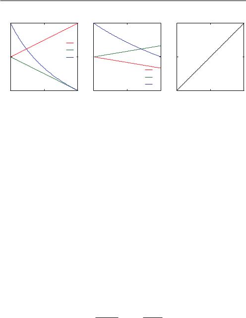
Fig. 7.8: Dependence of the spin-flip (SF) and non spin-flip (NSF) scattering and the magnetic scattering upon the initial polarization. If the flipping ratio from a known scatterer, i.e. the polarization, has been measured it is possible to extrapolate to ideal conditions with P = 1.
Provided the measured intensities have been corrected for background, all contributions can thus be separated by a set of rules:
dσ |
|
|
! |
dσ |
|
dσ |
|
|
|
dσ SF |
" |
|
|
|
|
|
dσ SF |
|
dσ SF |
|
|
|
|
|
|
|
|||
dΩpara |
= |
2 |
dΩ x |
+ dΩ y − 2dΩ z |
dσ NSF |
" |
|
|||||||
|
|
= −2 |
|
NSF |
|
NSF |
|
|
||||||
|
|
dΩ x |
+ dΩ y |
|
− 2dΩ z |
, |
||||||||
dσ |
|
3 |
!dσ SF |
dσ SF |
|
|
dσ SF |
|
(7.39) |
|||||
|
|
= |
2 |
3dΩ z − dΩ x |
|
− dΩ y |
" |
, |
|
|
||||
dΩinc |
|
|
|
|||||||||||
dσ |
|
dσ!SF |
1 dσ |
|
|
1 dσ |
|
|
|
|||||
|
|
= |
dΩ z − |
2 dΩ para − |
|
3 dΩ inc. |
|
|
|
|||||
dΩcoh |
|
|
|
|
||||||||||
All derivations above for the separation rules have assumed that the polarization of the neutrons is perfect, which is not the case in practice. The first question that then arises is how to determine the degree of polarization of a neutron beam, or, more generally, the quality of the ensemble comprised by the polarizer, flipper, and analyzer. Because coherent scattering is purely non spin-flip and the ratio of spin-flip to non spin-flip is exactly 2 for purely spin incoherent scattering the polarization can readily be determined by the flipping ratios, fNSF or fSF, obtained as the intensity ratios for the flipper off and on setting fNSF = I++/I+− or fSF = I+−/I++. For purely coherent scattering and perfect polarization fNSF = ∞ and for unpolarized neutrons fNSF = 1. A recommended and easy exercise is to show that
P = |
fNSF − 1 |
, |
P = 3 |
fSF − 1 |
. |
(7.40) |
|
fNSF + 1 |
|
|
fSF + 1 |
|
|
It is much more advisable to obtain the polarization from a coherent scatterer than from a spin incoherent scatterer, because if multiple scattering occurs, multiple spin flip will also occur, which is more difficult to handle. In order to obtain the flipping ratio for different scattering angles it is however required to either interpolate between Bragg peaks, or, better, to use a strong isotopically incoherent scatterer that does not produce spin incoherent scattering, such as ZrTi alloys (see Exercise 7.5).
Spin Dependent and Magnetic Scattering |
7.17 |
|
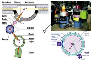
|
Fig. 7.9: (a,b) The IN12 triple axis spectrometer at ILL, Grenoble. Helmholtz coils or a magnet can be placed at the sample position. (c) Schematic drawing of Cryopad, a zero-field sample environment based on superconducting shielding that allows to measure the flipping ratios in all relative directions of P and P .
The second question that arises is how to correct for imperfections in the instrument and the polarization. This can be done by calibrating with a sample with known flipping ratio, measuring the real flipping ratio and then, by inverting Eq. 7.40 and solving for f(P ). A useful visualization of the required corrections is given in Fig. 7.8, where the relative non spin-flip and spin-flip intensities are represented.
7.5Instrumentation
Armed with a set of relations and devices we can now have a first glance at basic techniques that provide us insight into the materials under study, as well as some typical instrument designs that take advantage of polarization analysis.
The probably easiest method for studying magnetic scattering is diffraction of an unpolarized neutron beam. By measuring the scattering above and below the ordering temperature of the
material, that is in the magnetically ordered and in the paramagnetic state, and building the difference in the scattering intensities, one can obtain |MQ,order|2 − |MQ,para|2, see Appendix C.
Under the assumption that in the ordered state strong magnetic Bragg scattering occurs, whereas in the paramagnetic state only weak diffuse scattering is observed, the magnetic structure can in most cases be solved. A minor complication of this technique is that often the nuclear Bragg scattering is not perfectly subtracted, as the lattice constants might be slightly different in the ordered and paramagnetic state due to magnetostrictive effects.
A second elegant method is the so-called half polarized experiment, in which a polarized neutron beam is scattered by the sample but the polarization of the scattered neutrons is not analyzed. By applying a magnetic field parallel and antiparallel to the polarization, it is possible to
7.18 |
R. P. Hermann |
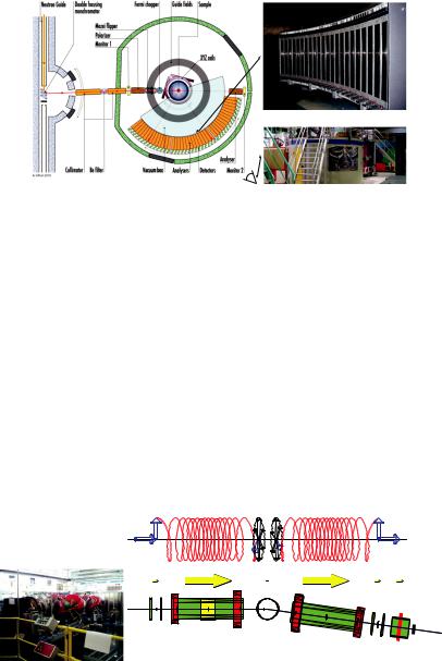
Fig. 7.10: The JCNS diffuse neutron spectrometer DNS with polarization analysis and time of flight option, at the FRM-II, Munich.
obtain the product of the nuclear and magnetic scattering amplitudes (see details in Appendix C, Eq. 7.45, by setting P = 1 and P = −1 and building the difference). The purely nuclear scattering can also be obtained by taking into account that the scattering in the direction parallel to the field is purely nuclear. The method works best if the magnetic moment can be saturated in field direction. This was illustrated in Fig. 7.3 for a half polarized small angle neutron scattering experiment on magnetically saturated nanoparticles [11].
A host of other methods exist and require more or less specialized instrumental setups. The conceptually simplest instrument is the triple axis spectrometer with polarizer and analyzer. A schematic representation is given in Fig. 7.6. In the basic version, with this instrument it is possible to measure the scattering intensities for one particular scattering vector. By using a spin flipper before (or after) the sample the spin-flip and non spin-flip intensities can be recorded. Further, the background can be efficiently measured by rocking the analyzer crystal by a few degrees, see for example Fig. 7.13 in Exercise 7.6. Depending on the requirements, a set of Helmholtz coils, see Fig. 7.7(b,c), can be placed around the sample in order to adiabatically bring the neutron polarization at the sample from the original direction of the polarizer to either x, y, or z direction and then back in the direction of the analyzer. Such instruments are very efficient for precise measurements in small regions of reciprocal space, but the measurement must be done step by step.
Multi detector instruments are more efficient when large volumes in reciprocal space must be probed. Examples of such instruments are D7, at the ILL in Grenoble, see Fig. 7.11, or DNS, at the FRM-II, in Munich, see Fig. 7.10. These instruments feature a bank of detectors for polarization analysis mounted in the horizontal scattering plane. The polarizer and the analyzers are magnetic multilayers separated by a layer of absorbing material, in which only one polarization is transported by total reflection. As there is a large number of detectors for polarization analysis, see right panel in Fig. 7.11, large amounts of multilayers had to be produced. A π-flipper is located in the incident beam between the polarizer and the sample. A particular challenge is to have a large area with a controlled guide field between the sample and the analyzers. As for the triple axis instruments, a set of Helmholtz coils can be located at the sample position in order to measure the spin-flip and non spin-flip scattering in different directions. Both of these instruments also feature a time-of-flight mode for separating the elastic and inelastic scattering, however inelastic polarized experiments are time consuming, as they require a factor 10 more
Spin Dependent and Magnetic Scattering |
7.19 |
Fig. 7.11: The D7 spectrometer at ILL, Grenoble, and its analyzer bank (top right) [17].
time for the 6 polarization components, and a factor 10-50 more due to the chopper duty cycle. For only two components and H spin incoherent scattering this is however nicely feasible.
Finally, polarized neutrons can also be used in a very clever way in order determine the energy transferred during the process of neutron scattering, in particular for quasielastic scattering studies. In general, quasior inelastic scattering instruments rely upon a determination of the wavelength of the neutrons before and after the scattering process. This can be bypassed by encoding this wavelength on the neutron itself, by using its spin. In such a so called neutron spin echo experiment, a polychromatic beam obtained by a velocity selector ( λ/λ 10 − 20%) is polarized longitudinally, i.e. the spin is parallel to k. At the entrance of a first magnetic precession coil with field in z, the neutron spin is flipped perpendicular to k and starts to precess for a distance l until reaching the sample. The precession rate depends on the field strength and the number of precession depends on the time spent in the coils, that is, on the neutron velocity or wavelength.
neutron spin |
spin rotation |
|
|
π/2 |
π |
π/2 |
|
|
magnetic field |
|
|
|
π |
|
|
π/2 |
sample |
|
|
flipper |
precession 1 |
π/2 |
detector |
|
precession 2 |
analyzer
Fig. 7.12: The JCNS J-NSE neutron spin-echo spectrometer at FRM II, left. Diagram of a neutron spin-echo spectrometer, right.
Neglecting scattering, if after the sample, the neutron travels in an exactly opposite magnetic field for the same distance l, the spin at the exit of this second magnetic precession coil will be exactly in the same direction as at the entrance of the first coil. More importantly, all neutrons, regardless of their wavelength will have recovered the same polarization as initially. Thus, the