

Schluesseltech_39 (1)
.pdf1.14 |
Th. Brückel |
Which type of radiation would you use to determine the charge density distribution in a solid?
X-rays
neutrons
electrons
light
How many neutrons per second impact on a sample with typical lateral dimensions of 1x1 cm in a typical neutron scattering experiment?
103
107
1012
1016
Which type of radiation would you use to determine the charge density distribution in a solid?
X-rays
neutrons
electrons
light
Introduction |
1.15 |
B E1.2 Comprehension
a.What is the difference between a scattering and an imaging experiment? When would you choose one over the other?
b.Why does one observe Laue spots when a “white” beam of X-rays is scattered from a single crystal? How about scattering from glass?
c.Why are neutrons sensitive to the magnetic order in a crystal?
d.Neutron scattering allows us to determine “where the atoms are and how the atoms move” in a condensed matter system. Other scattering probes include: light, x-rays,
electrons, -particles. Discuss qualitatively the strengths and weakness of these probes in comparison to neutron scattering.
e. CO2 has a bad reputation as green-house gas in the atmosphere. Could it, however, be useful as a scattering probe to replace neutrons? (A high flux of CO2 molecules could e.g. be obtained by an expansion of pressurised CO2 gas from a gas bottle through a nozzle - a flux many orders of magnitude higher than the neutron fluxes used in neutron scattering experiments!)
1.16 |
Th. Brückel |
C E1.3 |
Arithmetic Problem (optional): |
Huygens principle and coherence
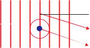
A plane wave of wavelength is incident on a pair of identical scatterers, which are separated by a distance L perpendicular to the wave propagation, see figure:


 L
L
According to the Huygens principle, spherical waves will be emitted from the two scatterers. In certain directions, these waves interfere constructively, i.e. the two scattered waves are in phase.
a)Calculate the angles , where interference maxima occur in the far field limit.
b)What happens to the interference maxima, if there is a broad distribution of wavelength in the incident wave, but the propagation direction remains well defined?
c)What happens to the interference maxima, if the wavelength of the incident wave is well defined, but there are many waves of different directions impinging on our scatterers?
d)How would you design an instrument to measure the distance L between the two scatterers, if light from a normal light bulb is being used as radiation? Which requirement does L have to fulfil in this case?
e)According to b) and c) monochromatization and collimation are important to obtain well resolved interference pattern. The corresponding requirements for the radiation are called longitudinal (b) and transverse (c) coherence, respectively. Discuss qualitatively the relation between coherence and resolution, i.e. in our example the ability of the apparatus designed in d) to determine the distance L between the scatterers.

2Neutron Sources
J. Voigt
Julich¨ Centre for Neutron Science 2
Forschungszentrum Julich¨ GmbH
Contents
2.1 |
Introduction |
2 |
|
2.2 |
How do we get free neutrons? |
3 |
|
|
2.2.1 |
Nuclear fission reactors . . . . . . . . . . . . . . . . . . . . . . . . . . . . . |
4 |
|
2.2.2 |
Spallation neutron source . . . . . . . . . . . . . . . . . . . . . . . . . . . |
5 |
|
2.2.3 |
Comparison of reactor and spallation sources . . . . . . . . . . . . . . . . . |
7 |
2.3 |
How do we make free neutrons useful? |
8 |
|
2.4 |
How do we bring the neutrons to the experiment? |
10 |
|
2.5 |
How do we detect neutrons? |
11 |
|
2.6 |
The take home messages |
12 |
|
Exercises |
|
14 |
|
Lecture Notes of the JCNS Laboratory Course Neutron Scattering (Forschungszentrum Julich,¨ 2011, all rights reserved)
2.2 |
J. Voigt |
2.1Introduction
Neutrons are an extremely versatile probe to investigate the fundamental properties of matter. The possible applications range from fundamental questions (e.g. electrical dipole moment of the neutron) over condensed matter physics and chemistry to material science and life sciences. The reason for this is threefold:
•The neutron is electrically neutral: hence it can penetrate deeply into matter and prove truly the bulk properties. If you use other massive particles to investigate the properties of matter such as α particles or electrons, you probe usually only the regions close to the surface. Even for x-ray, which is also considered as an bulk technique in general, you penetrate only several hundreds of nm, if you use wavelength delivered by an laboratory x-ray tube.
•The neutron interacts with the sample via nuclear forces: hence the interaction cross section depends on the internal structure of the nuclei in your sample and not on the mass or electric charge of the whole atom. Neutrons are sensitive more or less equally to heavy and light atoms, making them an ideal probe for samples containing hydrogen, carbon or oxygen next to any other heavier atom.
•The neutron has a large magnetic moment: hence it is extremely sensitive to the magnetic properties of your sample. The magnetic field created by the sample scatters the neutron and the analysis of the direction, into which the neutrons are scattered, and the number of scattered neutrons provides the information about the magnetic structure, the size of the magnetic moments and the coupling between different magnetic sites.
Neutrons are in particular useful, because their energy and wavelength corresponds very well with the interatomic distances and the typical excitations in condensed matter problems. We calculate the kinetic energy of a free neutron
Ekin = |
1 mv2 |
(2.1) |
||||||
|
2 |
|
|
|
|
|
||
= |
p2 |
|
|
|
(2.2) |
|||
2m |
||||||||
|
|
|
|
|||||
= |
|
h2 |
|
, |
(2.3) |
|||
|
2mλ |
2 |
||||||
|
|
|
|
|
|
|||
using the de Broglie relation, that expresses the wavelength of a quantum mechanical particle with momentum p:
|
λ = |
|
h |
|
|
|
|
|
|
|
(2.4) |
If we insert the natural constants, we get |
|
|p| |
|
|
|
|
|
||||
|
|
|
|
|
|
|
|
||||
|
|
|
|
|
|
|
|
|
|
|
|
E(λ) = |
|
|
|
|
|
˚ |
2 |
×λ |
−2 |
(2.5) |
|
81.805 meVA |
|
|
|||||||||
v(λ) = |
3956 |
ms |
−1 |
˚ |
|
× |
λ−1 |
(2.6) |
|||
|
|
|
|
A |
|
|
|
||||
In other words, if we provide neutrons with a wavelength |
|
˚ |
|||||||||
0.8 < λ < 20 A suitable for |
|||||||||||
resolving interatomic distances in condensed matter, these neutrons are also ideally suited to study the dynamics in the energy range 0.001 < E < 100 meV.
Neutron Sources |
2.3 |
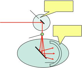
Apparently the properties of the neutrons make them a attractive probe for a wide variety of applications. In the reminder of the lecture I will try to answer the question, what the providers of neutrons, e.g. JCNS, FRM II, ILL, SNS..., can do to make their users happy. Therefore we first need do understand, what users want. We consider an generic neutron spectrometer, that allows to measure transfer of energy and momentum between neutron and the sample, see Fig. 2.1. How this is done, you will learn in the other lectures of the course and mainly during the practical part. The signal you get finally at the detector of your instrument can be expressed in
Primary
Monochromator spectrometer
Beam from |
|
|
a neutron source |
Secondary |
|
|
||
Sample |
spectrometer |
|
|
||
Analyzer |
|
|
Detector |
Fig. 2.1: Generic layout of a neu- |
|
tron spectrometer |
||
|
the following way:
Idet = I0 pr sec detσsampleVsample + background |
(2.7) |
I0 is the incident neutron flux, x denotes the efficiencies of the primary and the secondary spectrometer and the detector, σsample, Vsample is the cross section and the Volume of the sample, respectively. If you have an interesting scientific question that has not been answered yet, usually the both the cross section and volume are small. Hence to get good data, you need first an efficient instrument with a good signal to noise ratio, which detects ideally all and only the neutrons scattered by the sample. Second you need a low background that allows you to distinguish also tiny signals. And last but not least you need an intense source of neutrons, that brings a lot of useful neutrons to the instrument.
2.2 How do we get free neutrons?
The free neutron has a mean lifetime of about 900 s, hence it is necessary to produce the free neutrons as you run your experiment. While most nuclei are constituted to more then 50 % by neutrons, nuclear forces confine them and hence it is rather difficult to set neutrons free. Nowadays free neutron for scientific applications are released by nuclear reactions mainly in fission reactors or in spallation sources. Both routes require large scale facilities, that operate the source and provide state-of-art instrumentation. One example for the nuclear research reactor is the FRM II, where you will perform the practical part of the Laboratory Course. The most
2.4 |
J. Voigt |
powerful spallation source is the SNS installed at the Oak Ridge National Laboratory in the USA. The neutron as a free particle was discovered by James Chadwick in 1932, when he investigated the radiation from Beryllium illuminated with α particles. Finally he described the ongoing reaction as
24α +49 Be →612 C +01 n. |
(2.8) |
The uncharged particle in this equation was called neutron. The flux of free neutrons released by the reaction was about 100 n cm−2s−1. Such a small number would prevent any scattering experiment.
2.2.1Nuclear fission reactors
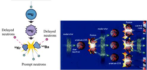
With the development of nuclear fission reactors in the 1940ies the situation changed. Using the fission reaction
235U +01 n → fission fragments + 2.52 ×01 n + 180MeV |
(2.9) |
the first experimental reactors released about 107 n cm−2s−1. Beside the investigation of the nuclear reaction, such a flux enabled the first scattering experiments with neutrons. In the following the thermal neutron flux increased dramatically until it saturated in the mid fifties. The still most powerful research reactor at the ILL became critical in 1974. The modern FRM II reactor has 0.5 × the flux of the ILL, but the thermal reactor power is lower by a factor 0.33 due to special core design. Furthermore, the flux of cold neutrons (see Sec. 2.3) is more or less the same. In the nuclear fission reaction eq. (2.9) a slow neutron is captured by an 235U
Fig. 2.2: Left) Schematic presentation of the fission process of 235U. Right) Controlled chain reaction in the nuclear reactor. Control rods reduce the number of slow neutrons to the amount just as necessary for the selfsustaining chain reaction. By the proper adjustment of the control rods position, the reaction may remains critical only with the inclusion of the delayed by a few seconds neutrons.
nucleus, which then splits into two fragments releasing 2 or 3 prompt neutrons, which carry an

Neutron Sources |
2.5 |
energy of 1.29 MeV. Each of this instantaneously (within 10 ns) emitted neutrons can fission another nuclei so that each of them will emit another 2 to 3 neutrons. The process is called chain reaction If the mass of the fissile material is larger than the so called critical mass MC the number of neutron will increase exponentially, leading to an uncontrollable reaction. If the mass of the fissile material is smaller than MC the number of neutrons will decrease over time and the nuclear chain reaction stops. If you want to sustain the nuclear reaction for a long time it is necessary to control the neutron flux such that the number of neutrons that drive the chain reaction remains constant. The control of the reactor is possible, if the nuclear reaction is not only triggered by the prompt neutrons. The fission fragments are also highly excited nuclei and relax to their ground state by the emission of neutrons among other nuclear reactions. Concerning only the prompt neutrons, the reactor is operated below its critical mass MC , but the delayed neutrons, which are comprised by the prompt neutrons, which are moderated in the cooling medium and the secondary neutrons from the fission fragments, sustain the chain reaction. The number of delayed neutrons is controlled by rods of neutron absorbing material (usually Boron), which can be inserted in the reactor core. Beside the control rods, which are used to steer the reactor, additional rods exist to fully stop the flux of neutrons and shut down the reactor.
With the development of the nuclear research reactors the thermal neutrons flux increased rapidly until it reached a flux Φ = 1015 n/cm2/s at the end of the 1960ties. An increase in neutron flux goes simultaneously with an increase in the thermal power of the reactor. However, the installations for extracting the neutrons suffers strongly by heat and radiation damage. Therefore the development of more powerful research reactors has stopped with the design of ILL reactor. The modern FRM II reactor has a very compact reactor core, which provides half of the thermal neutron flux using only one third of reactor power as compared to the ILL.
2.2.2 Spallation neutron source
Fig. 2.3: Schematic presentation of the spallation reaction
As an alternative to nuclear fission reactors neutrons can be released from the nucleus via spallation reactions, see Fig. 2.3. Here, high energy protons are accelerated onto a target made of a neutron rich material. Due to the large energy, the de Broglie wavelength
λ = |
h2 |
(2.10) |
2mE |
is so short, that the protons interacts with the single nucleons instead of the nucleus as a whole. The kicked nucleon may either leave the nucleus leading to an inter-nuclear cascade or may
2.6 |
J. Voigt |
be scattered by other nucleons leading to an intra-nuclear cascade. However, as a result of stage 1 of the spallation process, the nucleus is in a highly excited state. In stage 2 this energy is released by evaporation of a whole particle zoo, including neutrons. The neutron yield per spallation event depends on the target material. For typical materials 20-50 neutrons are released per spallation event. The deposited heat depends on the target material, too, and is on the order of 20 to 50 MeV/10n.
Concerning safety, the spallation source can never run out of control as no chain reaction is running. Neutrons are only produced, as long as the protons are accelerated onto the target. Even better, this feature can be used to impose a precise time structure on the neutron spectrum. The spallation process happens on a time scale of 10−15 s. Therefore the length of the proton pulse determines the length of the neutron pulse. If one measures the time of flight of a neutron from the source to the detector at your instrument, the neutron velocity can be determined, as the flight path is also known. You will learn more about time-of-flight spectroscopy and diffraction in the remaining lectures. Among the spallation source on distinguishes so called long pulse
a)
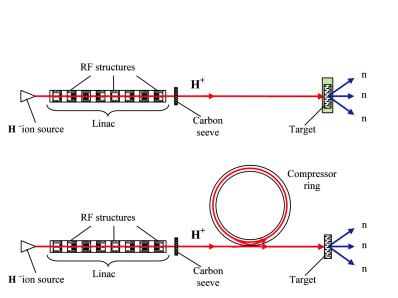
b)
Fig. 2.4: Schematic of a long pulse and a short pulse spallation source.
spallation sources (LPSS) and short pulse spallation sources. Using a linear accelerator a proton bunch with a width of several ms can be tailored. If the neutron pulse should be shorter, the protons have to be compressed. This is done by feeding the protons from the Linear accelerator into a synchrotron. The next bunch is then feed in, when the former one has revolved once, to make a denser proton bunch. Using the compressor, the 1μs duration pulses. While the latter type provides a higher peak flux, i. e., more neutrons in a short time intervall, the former type yields a significantly higher average neutron flux, in particular in the energy range that is typically used for diffraction experiments. Therefore certain experiments are better of at a SPSS, while the LPSS provides a more versatile spectrum and clearly is superior for ’slow’ neutrons. The most powerful existing spallation source, the 1 MW SNS at Oak Ridge is a SPSS,
Neutron Sources |
2.7 |
while the planned ESS in Lund, Sweden, will be a LPSS with 5 MW power.
2.2.3 Comparison of reactor and spallation sources
Comparing the different sources, we have to consider a number of features:
Neutron Flux Nowadays reactor source still provide the highest average neutron flux. This flux is still higher as the flux at the 1.4 MW SPSS. The 5 MW spallation source wil actually reach a similar average flux. However, for most experiments it is necessary, to select only a narrow range in energy or wavelength, respectively. At a pulsed source this can be done natively using time-of-flight monochromatization. Then not the average flux, but the peak flux, i. e., the flux during the proton pulse, counts. In that case, the monochromatic intensity at the spallation source can be higher.
Safety While the fissile material inside the reactor core of a research reactor is only a small fraction of the amount in a nuclear power plant, there is still a nuclear chain reaction ongoing, which in principle can run out of control. The spallation reaction is not possible without the operation of the accelerator and is therefore inherently safe.
As both source use nuclear reactions and create high energy particles, they both produce radioactive waste, which must be treated or stored after the operation of the facility. In case of the spallation source the waste has generally shorter life times.
Stability In fact, the operation of a proton accelerator is quite delicate. As already mentioned this makes the source very safe. On the other hand, sometimes it may also happen, that the proton beam is not available for quite some time during your allocated beam time. The neutron reactor runs usually very stable without interruption. Additionally the neutron flux is more stable at the reactor making it easier to compare individual measurements.
Technical feasibility The source neutron flux at a reactor could be increased only by an increase of the thermal power. There have been attempts to build a more powerful reactor in the US in the nineties, which has been abandoned for economical reasons. The heat removal from the core becomes extremely complex and also the radiation damage to the installations necessary for the extraction of the neutron is a severe issue. Therefore is unlikely, that higher power research reactors will be realized. At a spallation source the deposited heat For the SPSS exist similar arguments. The intense proton beam implants a large amount of heat in a very short time interval. Again the major problem is the removal of this heat. There seem to be a technological limit also for the short pulse spallation sources to increase their power far beyond the present state. For the long pulse spallation sources, the situation seems to be slightly relaxed. Since the heat is implanted during a longer time interval, the heat removal is facilitated. The 5 MW of power for the ESS could possibly increased up to 10 MW. There exist even estimates, that one could design a long pulse spallation target running at 20 MW. However, these are plans for the very far future, as already the ESS will be operational in the 2020ies only.
So far I have not considered the nuclear fusion reaction as a source for neutrons. Technologically this could be a technique at least as far in the future as a 20 MW spallation source. However, as seen from table 2.1 the deposited heat makes this reaction also a candidate for the over next generation of neutron sources.