

Digital design with CPLD applications and VHDL (R. Dueck, 2000)
.pdf130 C H A P T E R 4 • Introduction to PLDs and MAX+PLUS II
outputs are combined in an AND gate. Thus, the output would be HIGH if two out of three inputs were HIGH on both blocks labeled maj_vote. These blocks are complete designs in their own right, and thus form a lower level of the design hierarchy.
Default Symbols and User Libraries
K E Y T E R M S
Default symbol A graphical symbol that represents a PLD design as a block, showing only the design’s inputs and outputs. The symbol can be used as a component in any Graphic Design File.
User library A folder containing symbols that can be used in a gdf file.
Top level (of a hierarchy) The file in a hierarchy that contains components specified in other design files and is not itself a component of a higher-level file.
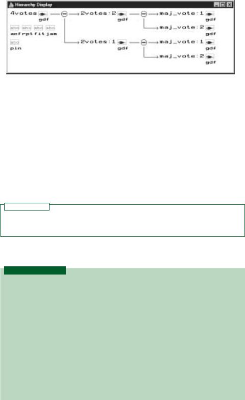
We can create a default symbol for the majority vote circuit of Figure 4.3 from the MAX PLUS II File menu, as shown in Figure 4.23. This action will create a symbol file with the same name as the Graphic Design File and the extension sym. Before creating the symbol, make sure that the gdf is saved and that the project is set to the current file.
FIGURE 4.23
Creating a Default Symbol
The symbol can be embedded into a gdf, as in Figure 4.22.
Before we can use the new symbol, we must make sure that MAX PLUS II knows where to find it. MAX PLUS II looks for a component first in the present working directory, then in the user library folders in the order of priority listed in the User Libraries dialog box.
To create a path to a user library, select User Libraries from the Options menu (Figure 4.24) in MAX PLUS II. In the resultant dialog box, shown in Figure 4.25, select the appropriate drive and directories by double-clicking on the name in the Directories box. When the desired directory appears in the Directory Name box, click

4.5 • Hierarchical Design |
131 |
FIGURE 4.24
Options Menu
FIGURE 4.25
User Libraries Dialog Box
Add, then OK.
132 C H A P T E R 4 • Introduction to PLDs and MAX+PLUS II
|
|
|
N O T E |
|
|
|
|
|
If you are using MAX PLUS II on a shared computer (e.g., in a computer lab), |
|
|
|
|
|
you should be aware that a library path that points to another user’s directory can |
|
|
|
|
|
cause MAX PLUS II to look there before (or instead of) looking in your directory, |
|
|
|
|
|
resulting in the apparent inability of MAX PLUS II to find your file. |
|
|
|
|
|
For example, suppose you have a file called g:\max2work\my_file.gdf, where |
|
|
|
|
|
g:\ is a network drive mapped exclusively to your user account. (i.e., everyone has |
|
|
|
|
|
a g:\ drive mapping, unique to their user account.) Further suppose that |
|
|
|
|
|
another user, against standard lab protocol, has created a file with the same name |
|
|
|
|
|
|
||
|
|
|
on the local hard drive: c:\max2work\my_file.gdf. (Don’t think this doesn’t hap- |
|
|
|
|
|
pen. It does.) |
|
|
|
|
|
At compile time, MAX PLUS II will look for my_file.gdf first in the direc- |
|
|
|
|
|
tory where the active project resides, then in the folders specified in the user library |
|
|
|
|
|
paths. If the user library path c:\max2work\ has a higher priority than |
|
|
|
|
|
g:\max2work\, it will compile the version of myfile.gdf found on the c: \drive. |
|
|
|
|
|
When you make changes to the copy on the g: \drive, they will not take effect be- |
|
|
|
|
|
cause the file on g:\ is not being compiled. |
|
|
|
|
|
To remedy this, delete the user libraries that point to local drives, such as a:\ or |
|
|
|
|
|
|
|
|
|
2votes.gdf |
|
|
|
|
|
maj_vote.gdf |
|
|
|
|
|
|
|
|
|
|
|
|
|
|
|
|
|
4votes.gdf |
Creating a Design Hierarchy |
|||
|
|
||||
|
|
The circuit in Figure 4.22 is saved as 2votes.gdf. If we double-click on either symbol la- |
|||
|
|
|
|
INPUT |
|
2votes |
||||||
|
|
|
|
|
|
|
|
|
|
|
|
|
A11 |
|
A1 |
|
|
|
|
|
|
|
|||
|
|
|
|
|
|
|
|
|
||||
|
INPUT |
|
|
|
|
|
|
|
||||
|
|
|
|
|
|
|
|
|
|
|
|
|
B11 |
|
|
B1 |
|
|
|
|
|
|
|
||
|
INPUT |
|
|
|
|
|
|
|
||||
C11 |
|
|
|
C1 |
|
|
|
|
|
|
|
|
|
|
|
|
|
|
|
|
|
||||
|
INPUT |
Y |
|
|
|
|
|
|
||||
A21 |
A2 |
|
|
|
||||||||
|
|
|||||||||||
|
|
|
|
|
|
|
|
|||||
INPUT |
|
|
|
|
|
|
|
|||||
|
|
|
|
|
|
|
|
|
|
|
|
|
B21 |
|
|
|
B2 |
|
|
|
|
|
|
|
|
|
|
INPUT |
|
|
|
AND2 |
||||||
C21 |
|
|
|
C2 |
|
|
|
|||||
|
|
|
|
|
|
|||||||
|
|
|
|
|
|
|||||||
|
|
|
|
|
|
|
|
|
|
|
OUTPUT |
|
|
|
|
|
|
|
|
|
|
|
|
||
|
|
|
|
INPUT |
|
2votes |
|
|
|
|
Y |
|
|
|
|
|
|
|
|
|
|
||||
|
|
|
|
|
|
|
|
|
|
|||
|
|
|
|
|
|
|
|
|
|
|
|
|
A12 |
|
|
A1 |
|
|
|
|
|
|
|
||
|
INPUT |
|
|
|
|
|
|
|
||||
|
|
|
|
|
|
|
|
|
|
|
|
|
B12 |
|
|
B1 |
|
|
|
|
|
|
|
||
|
INPUT |
|
|
|
|
|
|
|
||||
C12 |
|
|
|
C1 |
|
|
|
|
|
|
|
|
|
|
|
|
|
|
|
|
|
||||
|
INPUT |
Y |
|
|
|
|
|
|
||||
A22 |
A2 |
|
|
|
|
|
|
|||||
|
|
|
|
|
|
|
||||||
INPUT |
|
|
|
|
|
|
|
|||||
|
|
|
|
B2 |
|
|
|
|
|
|
|
|
B22 |
|
|
|
|
|
|
|
|
|
|||
|
INPUT |
|
|
|
|
|
|
|
||||
C22 |
|
|
|
C2 |
|
|
|
|
|
|
|
|
|
|
|
|
|
|
|
|
|
||||
|
|
|
|
|
|
|
|
|
||||
|
|
|
|
|
|
|
|
|
|
|
|
|
4.26
of Hierarchy (4votes.gdf)
beled maj vote, the MAX PLUS II Graphic Editor will bring the file maj_vote.gdf to the foreground. Thus, we say that 2votes.gdf is at the top level of the current hierarchy.
We can extend the hierarchy further by making a symbol for 2votes.gdf and embedding it in a higher-level file called 4votes.gdf, shown in Figure 4.26. This circuit generates a HIGH output if (two out of three of (A11, B11, C11) are HIGH AND two out of three of
4.6 • Text Design File (VHDL) |
133 |
FIGURE 4.27
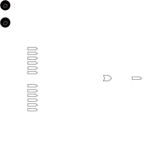
Hierarchy Display for Project “4votes”
(A21, B21, C21) are HIGH) OR the same is true for (A12, B12, C12) AND (A22, B22, C22). If we double-click on either symbol for 2votes, the Graphic Editor will bring the file 2votes.gdf to the foreground.
MAX PLUS II can display the hierarchy of a design. To see the hierarchy structure, click the Hierarchy icon on the MAX PLUS II toolbar (the yellow pyramid) or choose Hierarchy Display from the MAX PLUS II menu. Figure 4.27 shows the hierarchy for the project 4votes. Note that the highest level has two subdesigns, each of which breaks down further into two subdesigns. Thus, using hierarchical design and symbols for gdf or other design files allows us to create multiple instances of a basic design (maj_vote.gdf) and use it in many places.
N O T E
In order to correctly show the hierarchy display, the top-level file of the project (in this case 4votes.gdf) must be compiled first.
4.6 Text Design File (VHDL)
K E Y T E R M S
Hardware description language A computer language used to design digital circuits by entering text-based descriptions of the circuits.
AHDL (Altera Hardware Description Language) |
Altera’s proprietary text- |
entry design tool for PLDs. |
|
VHDL (VHSIC Hardware Description Language) |
An industry-standard com- |
puter language used to model digital circuits and produce programming data for PLDs.
VHSIC Very high speed integrated circuit
Syntax The “grammar” of a computer language. (i.e., the rules of construction of language statements)
ASICs (application specific integrated circuits) Integrated circuits that are constructed for a specific design purpose. The term could refer to a PLD, although it usually means a custom-designed fixed function device.
An alternative to schematic entry, and ultimately a more powerful PLD design technique is the use of a text-based design tool, or hardware description language, such as Altera’s
AHDL (Altera Hardware Description Language) or the industry-standard VHDL (VHSIC Hardware Description Language). A designer creates a text file, framed within a certain set of rules known as the syntax of the language and uses a compiler to create pro-

134 C H A P T E R 4 • Introduction to PLDs and MAX+PLUS II
gramming data much as he or she would with a Graphic Design File. Hardware description languages can be used to generate hardware for hierarchical designs, either as components in graphic or text files or as higher level design entities containing other designs.
AHDL, while very easy to use, has a much narrower application than VHDL because it is one of many proprietary tools on the market aimed at the programming requirements of a particular manufacturer’s line of CPLDs. Since VHDL is an industry-standard language and the MAX PLUS II compiler supports both languages, we will concentrate on VHDL.
VHDL was originally developed by defense contractors in the U.S. and is now the required standard for all ASICs (application specific integrated circuits) designed for the U.S. military. It has been standardized by the Institute of Electrical and Electronics Engineers (IEEE) and has been enjoying increasing popularity in the electronics design community. The original VHDL standard was written in 1987 and updated in 1993 (IEEE Std. 1076-1993). This standard and other related ones continue to undergo revision. The current status of Std. 1076 can be determined from the IEEE Standards web site at http://www.standards.ieee.org.
Entity and Architecture
K E Y T E R M S
Entity A VHDL structure that defines the inputs and outputs of a design.
Architecture A VHDL structure than defines the relationship between input, output, and internal signals or variables in a design.
Port A name assigned to an input or output of a VHDL design entity.
Mode (of a port) The kind of port, such as input or output.
Signal A name given to an internal connection in a VHDL architecture.
Variable A block of working memory used for internal calculation or storage in a
VHDL architecture.
Type A set of characteristics associated with a VHDL port name, signal, or variable that determines the allowable values of the port, signal, or variable.
Library A collection of VHDL design units that have been previously compiled.
Package A group of VHDL design elements that can be used by more than one
VHDL file.
IEEE Standard 1164 The standard which defines a variety of VHDL types and operations, including the STD_LOGIC and STD_LOGIC_VECTOR types.
Concurrent Simultaneous.
Concurrent signal assignment A relationship between an input and output port or signal in which the output is changed as soon as there is a change in input. If the file has more than one concurrent signal assignment, they are all evaluated simultaneously.
Selected signal assignment statement A concurrent signal assignment in VHDL in which a value is assigned to a signal, depending on the alternative values of another signal or variable.
Comment Explanatory text in a VHDL (or other computer language) file that is ignored by the computer at compile time.
Vector A group of digital signals or variables, usually related numerically, that can be treated as a single multibit variable.
Bit string literal A group of bits assigned to the elements of a vector, enclosed in double quotes (e.g., “001011”).
maj_vot2.vhd
4.28
Representation of a Entity
4.6 • Text Design File (VHDL) |
135 |
Every VHDL file requires at least two structures: an entity declaration and an architecture body. The entity declaration defines the external aspects of the VHDL function; that is, the input and output names and the name of the function. The architecture body defines the internal aspects; that is, how the inputs and outputs behave with respect to one another and with respect to other signals or functions that are internal only.
Let us examine the structure of a VHDL design for the majority vote circuit defined in Figure 4.1. The complete VHDL file for the majority vote circuit is shown next. The double dashes before the first two lines are to indicate that these lines are comments. There are also a few other comments to illustrate the use of VHDL.
——maj_vot2.vhd
——VHDL implementation of a majority vote circuit
——Library contains standard VHDL logic types LIBRARY ieee;
USE ieee.std_logic_1164.ALL;
——Entity defines inputs and outputs
ENTITY maj_vot2 IS
PORT (
a, b, c : IN STD LOGIC; y : OUT STD LOGIC);
END maj_vot2;
—— Architecture describes input/output relationship ARCHITECTURE majority OF maj_vot2 IS
BEGIN
y <= (a and b) or (b and c) or (a and c);
END majority;
N O T E
VHDL is not case-sensitive, so statements written in lowercase and uppercase are equivalent. For example, (Y A AND B;) is equivalent to (y a and b;). However, Altera’s style guidelines for VHDL suggest that all keywords, devices, constants, and primitives be capitalized and everything else be written in lowercase letters. The VHDL style guideline can be referred to in the MAX PLUS II Help menu.
The name of the entity, maj_vot2, is given in the first and last lines of the entity declaration. The VHDL file that contains this entity must be named maj_vot2.vhd. Figure 4.28 shows how the design entity looks if it is converted to a symbol for use in a Graphic Design File.
The Boolean equation for a 3-input majority vote circuit is Y AB BC AC. In the architecture body, we can write this operation as:
y <= (a and b) or (b and c) or (a and c);
The operator <= assigns the value of the right hand side of the equation to the left hand side. Whenever there is a change in a, b, or c, the statement is re-evaluated and the new value is assigned to y. Note that VHDL logical operators (such as and and or) have equal precedence, so we must make the order of precedence explicit with parentheses.
The Boolean equation above is an example of a concurrent signal assignment statement. Concurrent means “simultaneous.” The implication is that any number of concurrent signal assignments can be listed in a VHDL architecture body and the order in which they are evaluated does not depend on the order in which they are written, since all statements are concurrent. In this way, a concurrent structure imitates combinational hardware, where
136 C H A P T E R 4 • Introduction to PLDs and MAX+PLUS II
IN |
|
OUT |
INOUT |
CPLD |
BUFFER |
|
|
|
|
logic |
|
FIGURE 4.29
VHDL Port Modes
a change in one input that is common to several circuits makes all circuits change at the same time.
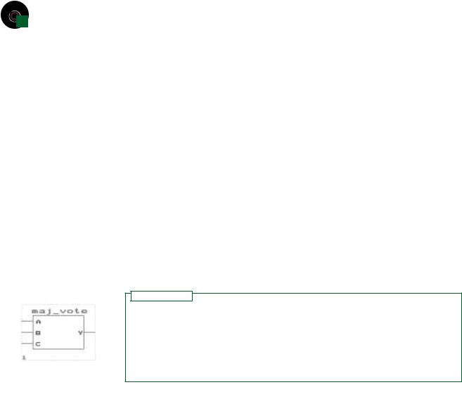
Enclosed in the entity declaration is a port definition. A port is a connection from the PLD to the outside world. Figure 4.29 shows the possible modes of a port. Mode IN refers
BUFFER
a |
|
|
|
|
|
x a and b; |
|||
|
|
|
|
|
|
|
|
||
b |
|
|
|
|
|
|
|
|
|
|
|
|
|
|
|
|
|
||
|
|
|
|
|
|
|
|
||
|
|
|
|
|
|
|
|
|
|
|
|
|
|
|
|
OUT |
|||
c |
|
|
|
|
|
|
y x or c; |
||
|
|
|
|
|
|
|
|
||
|
|
|
|
|
|
|
|
|
|
|
|
|
|
|
|
|
|
||
FIGURE 4.30
BUFFER and OUT Modes
to a port that is only for input. Mode OUT is output only. Mode INOUT is a bidirectional port, in which data can flow in either direction, based on the status of a control input. Mode BUFFER is a special case of OUT that has a feedback connection back into the CPLD logic that can be used as part of another Boolean expression.
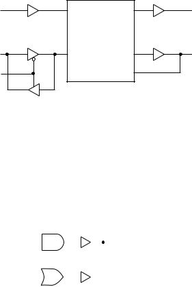
Figure 4.30 shows the difference between BUFFER and OUT modes. Port x (defined by x <= a and b;) must be of mode BUFFER because it is fed back and used as part of the expression for port y (defined by y <= x or c;). Port y can be of mode OUT since it has no feedback, only an output.
In addition to defining the port modes, the entity declaration also defines what type each port is. The type of a port, signal, or variable defines what values it is allowed to have. Three common types in VHDL are BIT, STD_LOGIC, and INTEGER. Multibit extensions of these types include BIT_VECTOR and STD_LOGIC_VECTOR.
Ports, signals and variables of type BIT can have a value of ‘0’ or ‘1’. When using these values, they must be enclosed in single quotes.
The STD_LOGIC (standard logic) type, also called IEEE Std.1164 Multi-Valued Logic, has been defined to give a broader range of output values than just ‘0’ and ‘1’. Any port, signal, or variable of type STD_LOGIC or STD_LOGIC_VECTOR can have any of the values listed below.
‘U’, –– Uninitialized ‘X’, –– Forcing Unknown ‘0’, –– Forcing 0
‘1’, –– Forcing 1 ‘Z’, –– High Impedance
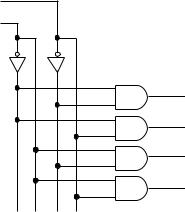
FIGURE 4.31
2-line-to-4-line Decoder
4.6 • Text Design File (VHDL) |
137 |
‘W’, –– Weak Unknown ‘L’, –– Weak 0
‘H’, –– Weak 1 ‘-’ –– Don’t care
“Forcing” levels are deemed to be the equivalent of a gate output. “Weak” levels are specified by a pull-up or pull-down resistor. (“Weak” levels are usually used in circuit modeling, where it is important to distinguish between gate outputs and pull-up/down. These levels will not be of importance to us.) The ‘Z’ state is used as the high-impedance state of a tristate buffer.
The majority of applications can be handled by ‘X’, ‘0’, ‘1’, and ‘Z’ values.
To use STD_LOGIC in a VHDL file, you must include the following reference to the VHDL library called ieee and the std_logic_1164 package before the entity declaration:
LIBRARY ieee;
USE ieee.std_logic_1164.ALL;
Table 4.1 Some Common VHDL Types
|
|
How |
|
Type |
Values |
Written |
Examples |
|
|
|
|
BIT |
0 or 1 |
Single quotes |
‘0’, ‘1’ |
|
|
|
|
STD_LOGIC |
U, X, 0, 1, Z, W, L, H, - |
Single quotes |
‘X’, ‘0’, ‘1’, ‘Z’ |
|
|
|
|
INTEGER |
Whole numbers |
No quotes |
4095, 7, -120, -1 |
|
|
|
|
BIT_VECTOR |
Multiple instances of 0 or 1 |
Double quotes |
“100110” |
|
|
|
|
STD_LOGIC_VECTOR |
Multiple instances of U, |
Double |
“1001100”, |
|
X, 0, 1, Z, W, L, H, - |
quotes |
“00ZZ11”, |
|
|
|
“ZZZZZZZZ” |
|
|
|
|
Why use STD_LOGIC rather than BIT, if we only use ‘0’ and ‘1’ values? The usual reason is for compatibility with existing VHDL components that might be used in our design entities. For example, the Altera Library of Parameterized Modules (LPM) contains
D0
D1
Y0
Y1
Y2
Y3

138 |
|
C H A P T E R |
4 • Introduction to PLDs and MAX+PLUS II |
|
|
|
predesigned components that are written using STD_LOGIC types. To include these com- |
|
|
|
ponents in a VHDL design, the design must be written with STD_LOGIC types, as well. |
|
|
|
The INTEGER type can take on whole-number values. When used in a VHDL file, an |
|
|
|
integer is written without quotes. Table 4.1 summarizes the BIT, STD_LOGIC, and INTE- |
|
|
|
GER types, as well as the BIT_VECTOR and STD_LOGIC_VECTOR types. |
|
|
|
|
EXAMPLE 4.3 |
Figure 4.31 shows the logic diagram of a 2-line-to-4-line decoder. The circuit detects the |
||
|
|
|
presence of a particular binary code and makes one and only one output HIGH, depending |
|
|
|
on the value of the 2-bit number D1D0. Write a VHDL file that describes the decoder. |
|
|
two inputs and four outputs, which are numerically related. We |
|
|
|
decode1.vhd |
|
|
|
|
as separate names, as we could the four outputs. Or, we could |
|
|
|
show the inputs and outputs as two groups of related ports, called vectors. The elements of |
|
|
|
the vector can be treated separately or as a group. |
|
|
|
Case 1: separate variables |
|
|
|
LIBRARY ieee; |
|
|
|
USE ieee.std_logic_1164.ALL; |
|
|
|
ENTITY decode1 IS |
PORT( |
|
|
d1, d0 |
: IN |
STD_LOGIC; |
y0, y1, y2, y3 |
: OUT |
STD_LOGIC); |
END decode1; |
|
|
decode2.vhd
decode2a.vhd
ARCHITECTURE decoder1 OF decode1 IS
BEGIN
y0 |
<= |
(not |
d1) |
and (not |
d0); |
|
y1 |
<= |
(not |
d1) |
and ( |
d0); |
|
y2 |
<= |
( |
d1) |
and |
(not d0); |
|
y3 |
<= |
( |
d1) |
and |
( |
d0); |
END decoder1;
Case 2: vectors (elements treated separately)
LIBRARY ieee;
USE ieee.std_logic_1164.ALL;
ENTITY decode2 IS |
|
|
|
|
PORT ( |
|
|
|
|
|
d |
: IN |
STD_LOGIC_VECTOR (1 downto 0); |
|
|
y |
: OUT STD_LOGIC_VECTOR (3 downto 0)); |
||
END decode2; |
|
|
|
|
ARCHITECTURE decoder2 OF decode2 IS |
|
|||
BEGIN |
|
|
|
|
y(0) |
<= |
(not |
d(1)) and (not d(0)); |
|
y(1) |
<= |
(not |
d(1)) and ( |
d(0)); |
y(2) |
<= |
( |
d(1)) and (not d(0)); |
|
y(3) |
<= |
( |
d(1)) and ( |
d(0)); |
END decoder2;
In Case 2, we specify the length of the vector by the construct (3 downto 0), indicating that Y3 is the leftmost bit in the vector. We could also use the constructs (0 to 3), (4 downto 1), or (1 to 4), depending on our requirements. Each individual element of the vector is specified by a number in parentheses.
Case 3: vectors (elements treated as a group)
—— decode2a.vhd
—— 4-channel decoder
4.6 • Text Design File (VHDL) |
139 |
—— Makes one and only one output HIGH for each
—— binary combination of (d1, d0).
LIBRARY ieee;
USE ieee.std_logic_1164.ALL;
ENTITY decode2a IS
PORT (
d : IN STD_LOGIC_VECTOR (1 downto 0); y : OUT STD_LOGIC_VECTOR (3 downto 0));
END decode2a;
ARCHITECTURE decoder OF decode2a IS
BEGIN
——Choose a signal assignment for y
——based on binary value of d
——Default case: all outputs deactivated WITH d SELECT
y <= “0001” WHEN “00”, “0010” WHEN “01”, “0100” WHEN “10”, “1000” WHEN “11”, “0000” WHEN others;
END decoder;
In Case 3, we use a selected signal assignment statement to assign a value to all bits of vector y for each combined value of vector d. For example, when d(1) 0 and d(0) 0, the values assigned to y are: y(3) 1, y(2) 0, y(1) 0, y(0) 0. Similar assignments are made for other values of d. The result is a construct that acts much like a truth table of the decoder circuit. The others clause is necessary to define a default case
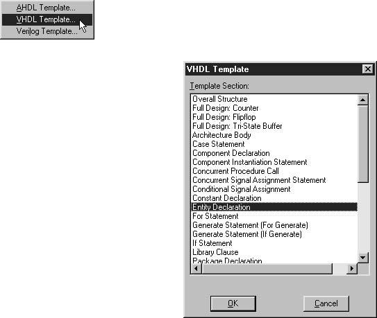
FIGURE 4.32
MAX PLUS II Template Menu
FIGURE 4.33
VHDL Template Dialog Box