

Digital design with CPLD applications and VHDL (R. Dueck, 2000)
.pdf10 |
C H A P T E R 1 • Basic Principles of Digital Systems |
3.Continue this process until the quotient is 0. The last remainder is the most significant bit of the binary number.
11/2 5 |
remainder 1 |
|
5/2 2 |
remainder 1 |
|
2/2 1 |
remainder 0 |
|
1/2 0 |
remainder 1 |
(MSB) |
To write the binary equivalent of the decimal number, read the remainders from the bottom up.
|
|
|
4610 1011102 |
|
|
|
|||
EXAMPLE 1.4 |
Use repeated division by 2 to convert 11510 to a binary number. |
|||
|
SOLUTION |
115/2 57 remainder 1 (LSB) |
||
|
|
57/2 |
28 remainder 1 |
|
|
|
28/2 |
14 |
remainder 0 |
|
|
14/2 7 |
remainder 0 |
|
|
|
7/2 3 |
remainder 1 |
|
|
|
3/2 1 |
remainder 1 |
|
|
|
1/2 0 remainder 1 (MSB) |
||
Read the remainders from bottom to top: 1110011.
11510 11100112
In any decimal-to-binary conversion, the number of bits in the binary number is the exponent of the smallest power of 2 that is larger than the decimal number.
For example, for the numbers 9210 and 4610,
27 128 92 |
7 bits: 1011100 |
26 64 46 |
6 bits: 101110 |
Fractional Binary Numbers
K E Y T E R M S
Radix point The generalized form of a decimal point. In any positional number system, the radix point marks the dividing line between positional multipliers that are positive and negative powers of the system’s number base.
Binary point A period (“.”) that marks the dividing line between positional multipliers that are positive and negative powers of 2 (e.g., first multiplier right of binary point 2 1; first multiplier left of binary point 20).
In the decimal system, fractional numbers use the same digits as whole numbers, but the digits are written to the right of the decimal point. The multipliers for these digits are negative powers of 10—10 1 (1/10), 10 2 (1/100), 10 3 (1/1000), and so on.
So it is in the binary system. Digits 0 and 1 are used to write fractional binary numbers, but the digits are to the right of the binary point—the binary equivalent of the decimal point. (The decimal point and binary point are special cases of the radix point, the general name for any such point in any number system.)

|
|
|
|
|
|
1.3 • |
The Binary Number System |
11 |
||
|
Each digit is multiplied by a positional factor that is a negative power of 2. The first |
|||||||||
|
four multipliers on either side of the binary point are: |
|
|
|
|
|||||
|
|
|
|
|
binary |
|
|
|
|
|
|
|
|
|
|
point |
|
|
|
|
|
|
23 |
22 |
21 |
20 |
|
2 1 |
2 2 |
2 3 |
2 4 |
|
|
8 |
4 |
2 |
1 |
|
1/2 |
1/4 |
1/8 |
1/16 |
|
|
|
|
|
|
||||||
EXAMPLE 1.5 |
Write the binary fraction 0.101101 as a decimal fraction. |
|
|
|
||||||
|
SOLUTION |
|
1 1/2 1/2 |
|
|
|
|
|
|
|
|
|
0 1/4 0 |
|
|
|
|
|
|
||
|
|
1 1/8 1/8 |
|
|
|
|
|
|
||
|
|
1 |
1/16 1/16 |
|
|
|
|
|
|
|
|
|
0 |
1/32 0 |
|
|
|
|
|
|
|
|
|
1 |
1/64 1/64 |
|
|
|
|
|
|
|
1/2 1/8 1/16 1/64 32/64 8/64 4/64 1/64
45/64
0.70312510
Fractional-Decimal-to-Fractional-Binary Conversion
Simple decimal fractions such as 0.5, 0.25, and 0.375 can be converted to binary fractions by a sum-of-powers method. The above decimal numbers can also be written 0.5 1/2, 0.25 1/4, and 0.375 3/8 1/4 1/8. These numbers can all be represented by negative powers of 2. Thus, in binary,
0.510 0.12
0.2510 0.012
0.37510 0.0112
The conversion process becomes more complicated if we try to convert decimal fractions that cannot be broken into powers of 2. For example, the number 1/5 0.210 cannot be exactly represented by a sum of negative powers of 2. (Try it.) For this type of number, we must use the method of repeated multiplication by 2.
Method:
1.Multiply the decimal fraction by 2 and note the integer part. The integer part is either 0 or 1 for any number between 0 and 0.999. . . . The integer part of the product is the first digit to the left of the binary point.
0.2 2 0.4 |
Integer part: 0 |
2.Discard the integer part of the previous product. Multiply the fractional part of the previous product by 2. Repeat step 1 until the fraction repeats or terminates.
0.4 2 0.8 |
Integer part: 0 |
0.8 2 1.6 |
Integer part: 1 |
0.6 2 1.2 |
Integer part: 1 |
0.2 2 0.4 |
Integer part: 0 |
(Fraction repeats; product is same as in step 1)

12 |
C H A P T E R 1 • Basic Principles of Digital Systems |
Read the above integer parts from top to bottom to obtain the fractional binary number. Thus, 0.210 0.00110011 . . .2 0.00112. The bar shows the portion of the digits that repeats.
EXAMPLE 1.6 |
Convert 0.9510 to its binary equivalent. |
|
|
|
SOLUTION |
0.95 2 1.90 |
Integer part: 1 |
|
|
0.90 2 1.80 |
Integer part: 1 |
|
|
0.80 2 1.60 |
Integer part: 1 |
|
|
0.60 2 1.20 |
Integer part: 1 |
|
|
0.20 2 0.40 |
Integer part: 0 |
|
|
0.40 2 0.80 |
Integer part: 0 |
0.80 2 1.60 Fraction repeats last four digits
0.9510 |
0.1111002 |
|
|
|
SECTION 1.3 REVIEW PROBLEMS
1.2.How many different binary numbers can be written with 6 bits?
1.3.How many can be written with 7 bits?
1.4.Write the sequence of 7-bit numbers from 1010000 to 1010111.
1.5.Write the decimal equivalents of the numbers written for Problem 1.4.
1.4
TABLE 1.4 Hex Digits and
Their Binary and Decimal
Equivalents
Hex |
Decimal |
Binary |
|
|
|
0 |
0 |
0000 |
1 |
1 |
0001 |
2 |
2 |
0010 |
3 |
3 |
0011 |
4 |
4 |
0100 |
5 |
5 |
0101 |
6 |
6 |
0110 |
7 |
7 |
0111 |
8 |
8 |
1000 |
9 |
9 |
1001 |
A |
10 |
1010 |
B |
11 |
1011 |
C |
12 |
1100 |
D |
13 |
1101 |
E |
14 |
1110 |
F |
15 |
1111 |
|
|
|
Hexadecimal Numbers
After binary numbers, hexadecimal (base 16) numbers are the most important numbers in digital applications. Hexadecimal, or hex, numbers are primarily used as a shorthand form of binary notation. Since 16 is a power of 2 (24 16), each hexadecimal digit can be converted directly to four binary digits. Hex numbers can pack more digital information into fewer digits.
Hex numbers have become particularly popular with the advent of small computers, which use binary data having 8, 16, or 32 bits. Such data can be represented by 2, 4, or 8 hexadecimal digits, respectively.
Counting in Hexadecimal
The positional multipliers in the hex system are powers of sixteen: 160 1, 161 16, 162 256, 163 4096, and so on.
We need 16 digits to write hex numbers; the decimal digits 0 through 9 are not sufficient. The usual convention is to use the capital letters A through F, each letter representing a number from 1010 through 1510. Table 1.4 shows how hexadecimal digits relate to their decimal and binary equivalents.
N O T E
Counting Rules for Hexadecimal Numbers:
1.Count in sequence from 0 to F in the least significant digit.
2.Add 1 to the next digit to the left and start over.
3.Repeat in all other columns.
For instance, the hex numbers between 19 and 22 are 19, 1A, 1B, 1C, 1D, 1E, 1F, 20, 21, 22. (The decimal equivalents of these numbers are 2510 through 3410.)

|
|
1.4 • Hexadecimal Numbers |
13 |
|
|
|
|
|
EXAMPLE 1.7 |
What is the next hexadecimal number after 999? After 99F? After 9FF? After FFF? |
|
|
|
SOLUTION The hexadecimal number after 999 is 99A. The number after 99F is 9A0. |
|
|
|
The number after 9FF is A00. The number after FFF is 1000. |
|
|
|
|
|
|
EXAMPLE 1.8 |
List the hexadecimal digits from 19016 to 20016, inclusive. |
|
|
|
SOLUTION The numbers follow the counting rules: Use all the digits in one position, |
|
|
|
add 1 to the digit one position left, and start over. |
|
|
|
For brevity, we will list only a few of the numbers in the sequence: |
|
190, 191, 192, . . . , 199, 19A, 19B, 19C, 19D, 19E, 19F, |
|
1A0, 1A1, 1A2, . . . , 1A9, 1AA, 1AB, 1AC, 1AD, 1AE, 1AF, |
|
1B0, 1B1, 1B2, . . . , 1B9, 1BA, 1BB, 1BC, 1BD, 1BE, 1BF, |
|
1C0, . . . , 1CF, 1D0, . . . , 1DF, 1E0, . . . , 1EF, 1F0, . . . , 1FF, 200 |
|
|
SECTION 1.4A REVIEW PROBLEMS
1.6.List the hexadecimal numbers from FA9 to FB0, inclusive.
1.7.List the hexadecimal numbers from 1F9 to 200, inclusive.
Hexadecimal-to-Decimal Conversion
To convert a number from hex to decimal, multiply each digit by its power-of-16 positional multiplier and add the products. In the following examples, hexadecimal numbers are indicated by a final “H” (e.g., 1F7H), rather than a “16” subscript.
EXAMPLE 1.9 |
Convert 7C6H to decimal. |
|
|
|
|
|
|
SOLUTION |
7 162 710 25610 179210 |
|
|||
|
|
C 161 1210 1610 19210 |
||||
|
|
6 160 610 110 610 |
|
|
||
|
|
|
|
|
|
|
|
|
199010 |
|
|
||
|
|
|
|
|||
EXAMPLE 1.10 |
Convert 1FD5H to decimal. |
|||||
|
SOLUTION |
1 163 110 409610 409610 |
||||
|
|
F 162 1510 25610 384010 |
||||
|
|
D 161 1310 1610 20810 |
||||
|
|
5 160 510 110 510 |
|
|||
|
|
|
|
|
|
|
814910 |
|
|
SECTION 1.4B REVIEW PROBLEM
1.8Convert the hexadecimal number A30F to its decimal equivalent.
Decimal-to-Hexadecimal Conversion
Decimal numbers can be converted to hex by the sum-of-weighted-hex-digits method or by repeated division by 16. The main difficulty we encounter in either method is

14 |
C H A P T E R |
1 • Basic Principles of Digital Systems |
|
|
|||
|
|
remembering to convert decimal numbers 10 through 15 into the equivalent hex digits, |
|||||
|
|
A through F. |
|
|
|
|
|
|
|
Sum of Weighted Hexadecimal Digits |
|
||||
|
|
This method is useful for simple conversions (about three digits). For example, the decimal |
|||||
|
|
number 35 is easily converted to the hex value 23. |
|
||||
|
|
|
3510 3210 310 (2 16) (3 1) 23H |
|
|||
|
|
|
|
|
|
|
|
|
EXAMPLE 1.11 |
Convert 17510 to hexadecimal. |
|
|
|||
|
|
SOLUTION |
|
|
25610 17510 1610 |
|
|
|
|
Since 256 162, the hexadecimal number will have two digits. |
|
||||
|
|
(11 16) 175 (10 16) |
|
||||
|
|
16 |
1 |
|
|
|
|
|
|
|
|
|
|
|
|
|
|
|
A |
|
|
175 (A 16) 175 160 15 |
|
|
|
|
|
|
|
|
|
|
|
16 |
1 |
|
|
|
|
|
|
|
|
|
|
175 ((A 16) (F 1)) |
|
|
|
|
A |
F |
|
|
|
|
|
|
|
|
|
175 (160 15) 0 |
|
|
|
|
|
|
|
||
|
|
|
|
|
|
|
|
Repeated Division by 16
Repeated division by 16 is a systematic decimal-to-hexadecimal conversion method that is not limited by the size of the number to be converted.
It is similar to the repeated-division-by-2 method used to convert decimal numbers to binary. Divide the decimal number by 16 and note the remainder, making sure to express it as a hex digit. Repeat the process until the quotient is zero. The last remainder is the most significant digit of the hex number.
EXAMPLE 1.12 |
Convert 3158110 to hexadecimal. |
|
|
||
|
SOLUTION |
31581/16 1973 remainder 13 (D) (LSD) |
|||
|
|
1973/16 |
123 |
remainder |
5 |
|
|
123/16 |
7 |
remainder 11 (B) |
|
|
|
7/16 |
0 |
remainder |
7 (MSD) |
|
|
|
3158110 7B5DH |
|
|
|
|
|
|
|
|
SECTION 1.4C REVIEW PROBLEM
1.9Convert the decimal number 8137 to its hexadecimal equivalent.
Conversions Between Hexadecimal and Binary
Table 1.4 shows all 16 hexadecimal digits and their decimal and binary equivalents. Note that for every possible 4-bit binary number, there is a hexadecimal equivalent.
Binary-to-hex and hex-to-binary conversions simply consist of making a conversion between each hex digit and its binary equivalent.

|
1.5 • Digital Waveforms |
15 |
|
|
|
EXAMPLE 1.13 |
Convert 7EF8H to its binary equivalent. |
|
|
SOLUTION Convert each digit individually to its equivalent value: |
|
|
7H 01112 |
|
|
EH 11102 |
|
|
FH 11112 |
|
|
8H 10002 |
|
|
The binary number is all the above binary numbers in sequence: |
|
|
7EF8H 1111110111110002 |
|
|
The leading zero (the MSB of 0111) has been left out. |
|
|
|
SECTION 1.4D REVIEW PROBLEMS
1.10Convert the hexadecimal number 934B to binary.
1.11Convert the binary number 11001000001101001001 to hexadecimal.
1.5Digital Waveforms
K E Y T E R M
Digital waveform A series of logic 1s and 0s plotted as a function of time.
The inputs and outputs of digital circuits often are not fixed logic levels but digital waveforms, where the input and output logic levels vary with time. There are three possible types of digital waveform. Periodic waveforms repeat the same pattern of logic levels over a specified period of time. Aperiodic waveforms do not repeat. Pulse waveforms follow a HIGH-LOW-HIGH or LOW-HIGH-LOW pattern and may be periodic or aperiodic.
Periodic Waveforms
K E Y T E R M S
Periodic waveform A time-varying sequence of logic HIGHs and LOWs that repeats over a specified period of time.
Period (T) Time required for a periodic waveform to repeat. Unit: seconds (s).
Frequency (f ) Number of times per second that a periodic waveform repeats. f 1/T Unit: Hertz (Hz).
Time HIGH (th) Time during one period that a waveform is in the HIGH state.
Unit: seconds (s).
Time LOW (tl) Time during one period that a waveform is in the LOW state.
Unit: seconds (s).
Duty cycle (DC) Fraction of the total period that a digital waveform is in the
HIGH state. DC th/T (often expressed as a percentage: %DC th/T 100%).
Periodic waveforms repeat the same pattern of HIGHs and LOWs over a specified period of time. The waveform may or may not be symmetrical; that is, it may or may not be HIGH and LOW for equal amounts of time.
16 |
C H A P T E R |
1 • Basic Principles of Digital Systems |
||
|
|
|
|
|
|
EXAMPLE 1.14 |
Calculate the time LOW, time HIGH, period, frequency, and percent duty cycle for |
||
|
|
each of the periodic waveforms in Figure 1.5. |
||
|
|
|
|
|
|
|
|
|
|
FIGURE 1.5
Example 1.14: Periodic Digital Waveforms
How are the waveforms similar? How do they differ?
SOLUTION
a.Time LOW: tl 3 ms Time HIGH: th 1 ms
Period: T tl th 3 ms 1 ms 4 ms Frequency: f 1/T 1/(4 ms) 0.25 kHz 250 Hz
Duty cycle: %DC (th/T) 100% (1 ms/4 ms) 100%
25%
(1 ms 1/1000 second; 1 kHz 1000 Hz.)
b.Time LOW: tl 2 ms Time HIGH: th 2 ms
Period: T tl th 2 ms 2 ms 4 ms Frequency: f 1/T 1/(4 ms) 0.25 kHz 250 Hz
Duty cycle: %DC (th/T) 100% (2 ms/ 4 ms) 100%
50%
c.Time LOW: tl 1 ms Time HIGH: th 3 ms
Period: T tl th 1 ms 3 ms 4 ms
Frequency: f 1/T 1/(4 ms) 0.25 kHz and 250 Hz Duty cycle: %DC (th/T) 100% (3 ms/ 4 ms) 100%
75%
The waveforms all have the same period but different duty cycles. A square waveform,
shown in Figure 1.5b, has a duty cycle of 50%. |
|
|
Aperiodic Waveforms
K E Y T E R M
Aperiodic waveform A time-varying sequence of logic HIGHs and LOWs that
does not repeat.
An aperiodic waveform does not repeat a pattern of 0s and 1s. Thus, the parameters of time HIGH, time LOW, frequency, period, and duty cycle have no meaning for an aperiodic waveform. Most waveforms of this type are one-of-a-kind specimens. (It is also worth noting that most digital waveforms are aperiodic.)

1.5 • Digital Waveforms |
17 |
Figure 1.6 shows some examples of aperiodic waveforms.
FIGURE 1.6
Aperiodic Digital Waveforms
EXAMPLE 1.15 |
A digital circuit generates the following strings of 0s and 1s: |
|
|
a. |
0011111101101011010000110000 |
|
b. |
0011001100110011001100110011 |
|
c. |
0000000011111111000000001111 |
|
d. 1011101110111011101110111011 |
|
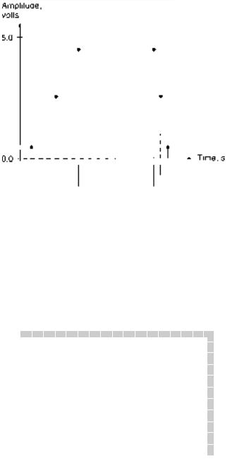
The time between two bits is always the same. Sketch the resulting digital waveform for each string of bits. Which waveforms are periodic and which are aperiodic?
SOLUTION Figure 1.7 shows the waveforms corresponding to the strings of bits above. The waveforms are easier to draw if you break up the bit strings into smaller groups of, say, 4 bits each. For instance:
a. 0011 1111 0110 1011 0100 0011 0000
All of the waveforms except Figure 1.7a are periodic.
FIGURE 1.7
Example 1.15: Waveforms
Pulse Waveforms
K E Y T E R M S
Pulse A momentary variation of voltage from one logic level to the opposite level and back again.
Amplitude The instantaneous voltage of a waveform. Often used to mean maximum amplitude, or peak voltage, of a pulse.
Edge The part of the pulse that represents the transition from one logic level to the other.
Rising edge The part of a pulse where the logic level is in transition from a LOW to a HIGH.
18 |
C H A P T E R 1 • Basic Principles of Digital Systems |
Falling edge The part of a pulse where the logic level is a transition from a HIGH to a LOW.
Leading edge The edge of a pulse that occurs earliest in time.
Trailing edge The edge of a pulse that occurs latest in time.
Pulse width (tw) Elapsed time from the 50% point of the leading edge of a pulse to the 50% point of the trailing edge.
Rise time (tr) Elapsed time from the 10% point to the 90% point of the rising edge of a pulse.
Fall time (tf ) Elapsed time from the 90% point to the 10% point of the falling edge of a pulse.
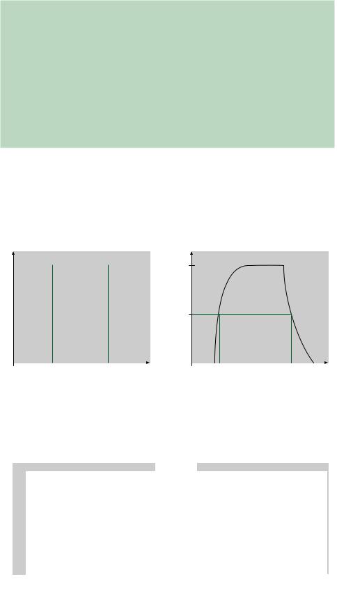
Figure 1.8 shows the forms of both an ideal and a nonideal pulse. The rising and falling edges of an ideal pulse are vertical. That is, the transitions between logic HIGH and LOW levels are instantaneous. There is no such thing as an ideal pulse in a real digital circuit. Circuit capacitance and other factors make the pulse more like the nonideal pulse in Figure 1.8b.
Pulses can be either positive-going or negative-going, as shown in Figure 1.9. In a pos- itive-going pulse, the measured logic level is normally LOW, goes HIGH for the duration
1 |
|
|
|
1 |
|
|
|
0.5
0 |
|
|
t |
0 |
|
|
t |
|
|
|
|
||||
|
t1 |
t2 |
|
t1 |
t2 |
||
a. Ideal pulse (instantaneous transitions) |
|
|
b. Nonideal pulse |
||||
FIGURE 1.8
Ideal and Nonideal Pulses
FIGURE 1.9
Pulse Edges
1.5 • Digital Waveforms |
19 |
of the pulse, and returns to the LOW state. A negative-going pulse acts in the opposite direction.
Nonideal pulses are measured in terms of several timing parameters. Figure 1.10 shows the 10%, 50%, and 90% points on the rising and falling edges of a nonideal pulse. (100% is the maximum amplitude of the pulse.)
FIGURE 1.10
Pulse Width, Rise Time, Fall
Time
|
The 50% points are used to measure pulse width because the edges of the pulse are not |
|
vertical. Without an agreed reference point, the pulse width is indeterminate. The 10% and |
|
90% points are used as references for the rise and fall times, since the edges of a nonideal |
|
pulse are nonlinear. Most of the nonlinearity is below the 10% or above the 90% point. |
|
|
EXAMPLE 1.16 |
Calculate the pulse width, rise time, and fall time of the pulse shown in Figure 1.11. |
FIGURE 1.11 |
|
Example 1.16: Pulse |
|
SOLUTION From the graph in Figure 1.11, read the times corresponding to the 10%, 50%, and 90% values of the pulse on both the leading and trailing edges.
Leading edge: |
10%: |
2 s |
Trailing edge: |
90%: |
20 s |
|
50%: |
5 s |
|
50%: |
25 s |
|
90%: |
8 s |
|
10%: |
30 s |