

Digital design with CPLD applications and VHDL (R. Dueck, 2000)
.pdfC H A P T E R 1
Basic Principles of Digital
Systems
O U T L I N E
1.1Digital Versus Analog Electronics
1.2Digital Logic Levels
1.3The Binary Number System
1.4Hexadecimal Numbers
1.5Digital Waveforms
C H A P T E R O B J E C T I V E S
Upon successful completion of this chapter, you will be able to:
•Describe some differences between analog and digital electronics.
•Understand the concept of HIGH and LOW logic levels.
•Explain the basic principles of a positional notation number system.
•Translate logic HIGHs and LOWs into binary numbers.
•Count in binary, decimal, or hexadecimal.
•Convert a number in binary, decimal, or hexadecimal to any of the other number bases.
•Calculate the fractional binary equivalent of any decimal number.
•Distinguish between the most significant bit and least significant bit of a binary number.
•Describe the difference between periodic, aperiodic, and pulse waveforms.
•Calculate the frequency, period, and duty cycle of a periodic digital waveform.
•Calculate the pulse width, rise time, and fall time of a digital pulse.
Digital electronics is the branch of electronics based on the combination and switching of voltages called logic levels. Any quantity in the outside world, such as temperature, pressure, or voltage, can be symbolized in a digital circuit by a group of logic voltages that,
taken together, represent a binary number. ■
Each logic level corresponds to a digit in the binary (base 2) number system. The bi- nary digits, or bits, 0 and 1, are sufficient to write any number, given enough places. The hexadecimal (base 16) number system is also important in digital systems. Since every combination of four binary digits can be uniquely represented as a hexadecimal digit, this system is often used as a compact way of writing binary information.
Inputs and outputs in digital circuits are not always static. Often they vary with time. Time-varying digital waveforms can have three forms:
1.Periodic waveforms, which repeat a pattern of logic 1s and 0s
2.Aperiodic waveforms, which do not repeat
3.Pulse waveforms, which produce a momentary variation from a constant logic level
1

2 |
C H A P T E R 1 • Basic Principles of Digital Systems |
1.1 Digital Versus Analog Electronics
K E Y T E R M S
Continuous Smoothly connected. An unbroken series of consecutive values with no instantaneous changes.
Discrete Separated into distinct segments or pieces. A series of discontinuous values.
Analog A way of representing some physical quantity, such as temperature or velocity, by a proportional continuous voltage or current. An analog voltage or current can have any value within a defined range.
Digital A way of representing a physical quantity by a series of binary numbers.
A digital representation can have only specific discrete values.
The study of electronics often is divided into two basic areas: analog and digital electronics. Analog electronics has a longer history and can be regarded as the “classical” branch of electronics. Digital electronics, although newer, has achieved greater prominence through the advent of the computer age. The modern revolution in microcomputer chips, as part of everything from personal computers to cars and coffee makers, is founded almost entirely on digital electronics.
The main difference between analog and digital electronics can be stated simply. Analog voltages or currents are continuously variable between defined values, and digital voltages or currents can vary only by distinct, or discrete, steps.
Some keywords highlight the differences between digital and analog electronics:
Analog |
Digital |
Continuously variable |
Discrete steps |
Amplification |
Switching |
Voltages |
Numbers |
An example often used to illustrate the difference between analog and digital devices is the comparison between a light dimmer and a light switch. A light dimmer is an analog device, since it can make the light it controls vary in brightness anywhere within a defined range of values. The light can be fully on, fully off, or at some brightness level in between. A light switch is a digital device, since it can turn the light on or off, but there is no value in between those two states.
The light switch/light dimmer analogy, although easy to understand, does not show any particular advantage to the digital device. If anything, it makes the digital device seem limited.
One modern application in which a digital device is clearly superior to an analog one is digital audio reproduction. Compact disc players have achieved their high level of popularity because of the accurate and noise-free way in which they reproduce recorded music. This high quality of sound is possible because the music is stored, not as a magnetic copy of the sound vibrations, as in analog tapes, but as a series of numbers that represent amplitude steps in the sound waves.
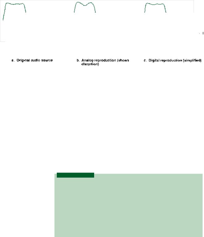
Figure 1.1 shows a sound waveform and its representation in both analog and digital forms.
The analog voltage, shown in Figure 1.1b, is a copy of the original waveform and introduces distortion both in the storage and playback processes. (Think of how a photocopy deteriorates in quality if you make a copy of a copy, then a copy of the new copy, and so on. It doesn’t take long before you can’t read the fine print.)
A digital audio system doesn’t make a copy of the waveform, but rather stores a code (a series of amplitude numbers) that tells the compact disc player how to re-create the original sound every time a disc is played. During the recording process, the sound waveform
|
|
|
1.2 • Digital Logic Levels |
3 |
|
|
|
|
|
|
|
|
|
|
|
|
|
FIGURE 1.1
Digital and Analog Sound Reproduction
is “sampled” at precise intervals. The recording transforms each sample into a digital number corresponding to the amplitude of the sound at that point.
The “samples” (the voltages represented by the vertical bars) of the digitized audio waveform shown in Figure 1.1c are much more widely spaced than they would be in a real digital audio system. They are shown this way to give the general idea of a digitized waveform. In real digital audio systems, each amplitude value can be indicated by a number having as many as 16,000 to 65,000 possible values. Such a large number of possible values means the voltage difference between any two consecutive digital numbers is very small. The numbers can thus correspond extremely closely to the actual amplitude of the sound waveform. If the spacing between the samples is made small enough, the reproduced waveform is almost exactly the same as the original.
SECTION 1.1 REVIEW PROBLEM
1.1 What is the basic difference between analog and digital audio reproduction?
1.2Digital Logic Levels
K E Y T E R M S
Logic level A voltage level that represents a defined digital state in an electronic
circuit. |
|
Logic HIGH (or logic 1) |
The higher of two voltages in a digital system with two |
logic levels. |
|
Logic LOW (or logic 0) |
The lower of two voltages in a digital system with two |
logic levels. |
|
Positive logic A system in which logic LOW represents binary digit 0 and logic
HIGH represents binary digit 1.
Negative logic A system in which logic LOW represents binary digit 1 and logic
HIGH represents binary digit 0.
Digitally represented quantities, such as the amplitude of an audio waveform, are usually represented by binary, or base 2, numbers. When we want to describe a digital quantity electronically, we need to have a system that uses voltages or currents to symbolize binary numbers.
The binary number system has only two digits, 0 and 1. Each of these digits can be denoted by a different voltage called a logic level. For a system having two logic levels, the
4 |
C H A P T E R 1 • Basic Principles of Digital Systems |
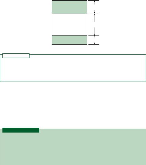
FIGURE 1.2
Logic Levels Based on 5 V and 0 V
lower voltage (usually 0 volts) is called a logic LOW or logic 0 and represents the digit 0. The higher voltage (traditionally 5 V, but in some systems a specific value such as 1.8 V, 2.5 V or 3.3 V) is called a logic HIGH or logic 1, which symbolizes the digit 1. Except for some allowable tolerance, as shown in Figure 1.2, the range of voltages between HIGH and LOW logic levels is undefined.
5 V
Logic HIGH
2 V
Undefined
0.8 V
Logic LOW
0 V
N O T E
For the voltages in Figure 1.2:
5 V Logic HIGH 1
0 V Logic LOW 0
The system assigning the digit 1 to a logic HIGH and digit 0 to logic LOW is called positive logic. Throughout the remainder of this text, logic levels will be referred to as HIGH/LOW or 1/0 interchangeably.
(A complementary system, called negative logic, also exists that makes the assignment the other way around.)
1.3 The Binary Number System
K E Y T E R M S
Binary number system A number system used extensively in digital systems, based on the number 2. It uses two digits, 0 and 1, to write any number.
Positional notation A system of writing numbers where the value of a digit depends not only on the digit, but also on its placement within a number.
Bit Binary digit. A 0 or a 1.
Positional Notation
The binary number system is based on the number 2. This means that we can write any number using only two binary digits (or bits), 0 and 1. Compare this to the decimal system, which is based on the number 10, where we can write any number with only ten decimal digits, 0 to 9.
The binary and decimal systems are both positional notation systems; the value of a digit in either system depends on its placement within a number. In the decimal number 845, the digit 4 really means 40, whereas in the number 9426, the digit 4 really means 400 (845 800 40 5; 9426 9000 400 20 6). The value of the digit is determined by what the digit is as well as where it is.
In the decimal system, a digit in the position immediately to the left of the decimal point is multiplied by 1 (100). A digit two positions to the left of the decimal point is mul-

1.3 • The Binary Number System |
5 |
tiplied by 10 (101). A digit in the next position left is multiplied by 100 (102). The positional multipliers, as you move left from the decimal point, are ascending powers of 10.
The same idea applies in the binary system, except that the positional multipliers are powers of 2 (20 1, 21 2, 22 4, 23 8, 24 16, 25 32, . . .). For example, the binary number 101 has the decimal equivalent:
|
|
(1 22) (0 21) (1 20) |
||
|
(1 4) |
(0 2) |
(1 1) |
|
|
|
4 |
0 |
1 |
|
|
5 |
|
|
|
|
|||
EXAMPLE 1.1 |
Calculate the decimal equivalents of the binary numbers 1010, 111, and 10010. |
|||
SOLUTIONS 1010 (1 23) (0 22) (1 21) (0 20)
(1 8) (0 4) (1 2) (0 1)
8 2 10 111 (1 22) (1 21) (1 20)
(1 4) (1 2) (1 1)
4 2 1 7 10010 (1 24) (0 23) (0 22) (1 21) (0 20)
(1 16) (0 8) (0 4) (1 2) (0 1)
16 2 18 |
|
|
Binary Inputs
K E Y T E R M S
Most significant bit The leftmost bit in a binary number. This bit has the number’s largest positional multiplier.
Least significant bit The rightmost bit of a binary number. This bit has the number’s smallest positional multiplier.
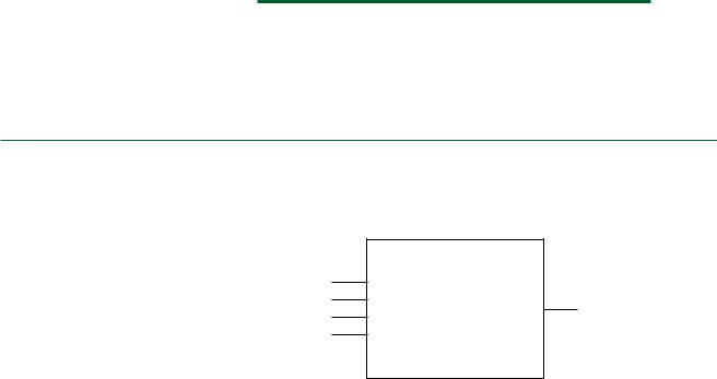
A major class of digital circuits, called combinational logic, operates by accepting logic levels at one or more input terminals and producing a logic level at an output. In the analysis and design of such circuits, it is frequently necessary to find the output logic level of a circuit for all possible combinations of input logic levels.
The digital circuit in the black box in Figure 1.3 has three inputs. Each input can have two possible states, LOW or HIGH, which can be represented by positive logic as 0 or 1. The number of possible input combinations is 23 8. (In general, a circuit with n binary inputs has 2n input combinations, ranging from 0 to 2n 1.) Table 1.1 shows a list of these combinations, both as logic levels and binary numbers, and their decimal equivalents.
FIGURE 1.3
3-Input Digital Circuit
6 |
C H A P T E R 1 • Basic Principles of Digital Systems |
|
|
|
|
|||
|
|
TABLE 1.1 Possible Input Combinations for a 3-Input Digital Circuit |
||||||
|
|
|
|
|
|
|
|
|
|
|
|
Logic Level |
|
Binary Value |
|
Decimal Equivalent |
|
|
|
|
|
|
|
|
|
|
|
|
A |
B |
C |
A |
B |
C |
|
|
|
L |
L |
L |
0 |
0 |
0 |
0 |
|
|
L |
L |
H |
0 |
0 |
1 |
1 |
|
|
L |
H |
L |
0 |
1 |
0 |
2 |
|
|
L |
H |
H |
0 |
1 |
1 |
3 |
|
|
H |
L |
L |
1 |
0 |
0 |
4 |
|
|
H |
L |
H |
1 |
0 |
1 |
5 |
|
|
H |
H |
L |
1 |
1 |
0 |
6 |
|
|
H |
H |
H |
1 |
1 |
1 |
7 |
|
|
|
|
|
|
|
|
|
A list of output logic levels corresponding to all possible input combinations, applied in ascending binary order, is called a truth table. This is a standard form for showing the function of a digital circuit.
The input bits on each line of Table 1.1 can be read from left to right as a series of 3- bit binary numbers. The numerical values of these eight input combinations range from 0 to 7 (2n possible input combinations, having decimal equivalents ranging from 0 to 2n 1) in decimal.
Bit A is called the most significant bit (MSB), and bit C is called the least significant bit (LSB). As these terms imply, a change in bit A is more significant, since it has the greatest effect on the number of which it is part.
Table 1.2 shows the effect of changing each of these bits in a 3-bit binary number and compares the changed number to the original by showing the difference in magnitude. A change in the MSB of any 3-bit number results in a difference of 4. A change in the LSB of any binary number results in a difference of 1. (Try it with a few different numbers.)
TABLE 1.2 Effect of Changing the LSB and MSB of a Binary Number
|
A |
B |
C |
Decimal |
|
|
|
|
|
|
|
Original |
0 |
1 |
1 |
3 |
|
Change MSB |
1 |
1 |
1 |
7 |
Difference 4 |
Change LSB |
0 |
1 |
0 |
2 |
Difference 1 |
|
|
|
|
|
|
EXAMPLE 1.2 |
Figure 1.4 shows a 4-input digital circuit. List all the possible binary input combinations to |
|
|
this circuit and their decimal equivalents. What is the value of the MSB? |
|
|
Inputs |
Outputs |
Digital circuit
A (MSB)
B
Y
C
D (LSB)
FIGURE 1.4
Example 1.2: 4-Input Digital Circuit

1.3 • The Binary Number System |
7 |
SOLUTION Since there are four inputs, there will be 24 16 possible input combinations, ranging from 0000 to 1111 (0 to 15 in decimal). Table 1.3 shows the list of all possible input combinations.
The MSB has a value of 8 (decimal).
TABLE 1.3 Possible Input
Combinations for a 4-Input Digital Circuit
A |
B |
C |
D |
Decimal |
|
|
|
|
|
0 |
0 |
0 |
0 |
0 |
0 |
0 |
0 |
1 |
1 |
0 |
0 |
1 |
0 |
2 |
0 |
0 |
1 |
1 |
3 |
0 |
1 |
0 |
0 |
4 |
0 |
1 |
0 |
1 |
5 |
0 |
1 |
1 |
0 |
6 |
0 |
1 |
1 |
1 |
7 |
1 |
0 |
0 |
0 |
8 |
1 |
0 |
0 |
1 |
9 |
1 |
0 |
1 |
0 |
10 |
1 |
0 |
1 |
1 |
11 |
1 |
1 |
0 |
0 |
12 |
1 |
1 |
0 |
1 |
13 |
1 |
1 |
1 |
0 |
14 |
1 |
1 |
1 |
1 |
15 |
Knowing how to construct a binary sequence is a very important skill when working with digital logic systems. Two ways to do this are:
1.Learn to count in binary. You should know all the binary numbers from 0000 to 1111 and their decimal equivalents (0 to 15). Make this your first goal in learning the basics of digital systems.
Each binary number is a unique representation of its decimal equivalent. You can work out the decimal value of a binary number by adding the weighted values of all the bits.
For instance, the binary equivalent of the decimal sequence 0, 1, 2, 3 can be written using two bits: the 1’s bit and the 2’s bit. The binary count sequence is:
00 ( 0 0)
01 ( 0 1)
10( 2 0)
11( 2 1)
To count beyond this, you need another bit: the 4’s bit. The decimal sequence 4, 5, 6, 7 has the binary equivalents:
100 ( 4 0 0)
101 ( 4 0 1)
110 ( 4 2 0)
111 ( 4 2 1)
The two least significant bits of this sequence are the same as the bits in the 0 to 3 sequence; a repeating pattern has been generated.
8 |
C H A P T E R 1 • Basic Principles of Digital Systems |
The sequence from 8 to 15 requires yet another bit: the 8’s bit. The three LSBs of this sequence repeat the 0 to 7 sequence. The binary equivalents of 8 to 15 are:
1000 ( 8 0 0 0)
1001 ( 8 0 0 1)
1010 ( 8 0 2 0)
1011 ( 8 0 2 1)
1100 ( 8 4 0 0)
1101 ( 8 4 0 1)
1110 ( 8 4 2 0)
1111 ( 8 4 2 1)
Practice writing out the binary sequence until it becomes familiar. In the 0 to 15 sequence, it is standard practice to write each number as a 4-bit value, as in Example 1.2, so that all numbers have the same number of bits. Numbers up to 7 have leading zeros to pad them out to 4 bits.
This convention has developed because each bit has a physical location in a digital circuit; we know a particular bit is logic 0 because we can measure 0 V at a particular point in a circuit. A bit with a value of 0 doesn’t go away just because there is not a 1 at a more significant location.
While you are still learning to count in binary, you can use a second method.
2.Follow a simple repetitive pattern. Look at Tables 1.1 and 1.3 again. Notice that the least significant bit follows a pattern. The bits alternate with every line, producing the pattern 0, 1, 0, 1, . . . . The 2’s bit alternates every two lines: 0, 0, 1, 1, 0, 0, 1, 1, . . . . The 4’s bit alternates every four lines: 0, 0, 0, 0, 1, 1, 1, 1, . . . . This pattern can be expanded to cover any number of bits, with the number of lines between alternations doubling with each bit to the left.
Decimal-to-Binary Conversion
There are two methods commonly used to convert decimal numbers to binary: sum of powers of 2 and repeated division by 2.
Sum of Powers of 2
You can convert a decimal number to binary by adding up powers of 2 by inspection, adding bits as you need them to fill up the total value of the number. For example, convert 5710 to binary.
6410 5710 3210
•We see that 32 ( 25) is the largest power of two that is smaller than 57. Set the 32’s bit to 1 and subtract 32 from the original number, as shown below.
57 32 25
•The largest power of two that is less than 25 is 16. Set the 16’s bit to 1 and subtract 16 from the accumulated total.
25 16 9
•8 is the largest power of two that is less than 9. Set the 8’s bit to 1 and subtract 8 from the total.
9 8 1
•4 is greater than the remaining total. Set the 4’s bit to 0.
•2 is greater than the remaining total. Set the 2’s bit to 0.
1.3 • The Binary Number System |
9 |
•1 is left over. Set the 1’s bit to 1 and subtract 1.
11 0
•Conversion is complete when there is nothing left to subtract. Any remaining bits should be set to 0.
32 |
16 |
8 |
4 |
2 |
1 |
|
|
|
|
|
|
|
|
|
|
|
|
– 32 = 25 |
|
1 |
|
|
|
|
|
57 |
|||
|
|
|
|
|
|
|
|
|
|
32 |
16 |
8 |
4 |
2 |
1 |
|
|
|
|
|
|
|
|
|
|
|
|
|
|
|
1 |
1 |
|
|
|
|
57 |
– (32 |
+ 16) = 9 |
|
|
|
|
|
|
|
|
|
|
32 |
16 |
8 |
4 |
2 |
1 |
|
|
|
|
|
|
|
|
|
|
|
|
|
|
1 |
1 |
1 |
|
|
|
57 – (32 |
+ 16 + 8) = 1 |
||
|
|
|
|
|
|
|
|
|
|
32 |
16 |
8 |
4 |
2 |
1 |
|
|
|
|
|
|
|
|
|
|
|
|
|
|
1 |
1 |
1 |
0 |
0 |
1 |
57 – (32 |
+ 16 + 8 + 1) = 0 |
||
|
|
|
|
|
|
|
|
|
|
|
|
|
|
|
|
|
5710 = 1110012 |
|
|||
|
|
|
|
|
|
|
|
|
|
|
|
EXAMPLE 1.3 |
Convert 9210 to binary using the sum-of-powers-of-2 method. |
|
|||||||||
|
SOLUTION |
128 92 64 |
|
|
|
|
|
||||
|
64 |
32 |
16 |
8 |
4 |
2 |
1 |
|
|
||
|
|
|
|
|
|
|
|
|
|
|
|
|
|
1 |
|
|
|
|
|
|
|
92 – 64 = 28 |
|
|
|
|
|
|
|
|
|
|
|
|
|
|
64 |
32 |
16 |
8 |
4 |
2 |
1 |
|
|
||
|
|
|
|
|
|
|
|
|
|
|
|
|
|
1 |
0 |
1 |
|
|
|
|
|
92 – (64 + 16) = 12 |
|
|
|
|
|
|
|
|
|
|
|
|
|
|
64 |
32 |
16 |
8 |
4 |
2 |
1 |
|
|
||
|
|
|
|
|
|
|
|
|
|
|
|
|
|
1 |
0 |
1 |
1 |
|
|
|
|
92 – (64 + 16 + 8) = 4 |
|
|
|
|
|
|
|
|
|
|
|
|
|
|
64 |
32 |
16 |
8 |
4 |
2 |
1 |
|
|
||
|
|
|
|
|
|
|
|
|
|
|
|
|
|
1 |
0 |
1 |
1 |
1 |
|
0 |
0 |
92 – (64 + 16 + 8 + 4) = 0 |
|
|
|
|
|
|
|
|
|
|
|
|
|
|
|
|
|
|
|
|
|
|
9210 = 10111002 |
|
|
Repeated Division by 2
Any decimal number divided by 2 will leave a remainder of 0 or 1. Repeated division by 2 will leave a string of 0s and 1s that become the binary equivalent of the decimal number. Let us use this method to convert 4610 to binary.
1. Divide the decimal number by 2 and note the remainder.
46/2 23 remainder 0 (LSB)
The remainder is the least significant bit of the binary equivalent of 46.
2.Divide the quotient from the previous division and note the remainder. The remainder is the second LSB.
23/2 11 remainder 1