

8.2 The Main Reasons for CE102, RE102, and RS103 Test Failures |
317 |
Round hole
Fan power cable
|
Case |
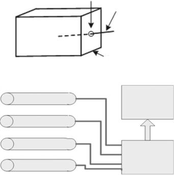
Fig. 8.6 Fan power cable and structure of the case |
|
Sensor |
Signal |
|
Display Terminal |
Sensor |
|
Sensor |
|
|
Signal |
|
Processing |
Sensor |
Module |
Fig. 8.7 Composition of the sensor equipment |
|
If the shielding of the case is continuous, i.e., there is no opening in the conductive case, then the shielding of the case shall be very effective in theory. However, any opening such as wires and holes can greatly reduce the shielding effectiveness.
8.2.3 RS103 Test
Example 8.4 In the RS103 test of certain sensor-type equipment, the 200 MHz–1 GHz susceptibility test was failed. And the higher the frequency, the more susceptive the equipment. The equipment was used to measure the change of a physical variable through a sensor. The change was then converted into an electrical signal and transmitted to the processor, as shown in Fig. 8.7.
In order to find the susceptive object and the coupling path, the copper mesh was used to cover the display module, the processing module, the interconnection cable, and the sensor of the product one by one, and the RS103 test was then performed. The test results showed that when the copper mesh covered the sensor and the transmission cable, the anti-interference ability of the equipment was improved. Therefore, it could
318 |
8 EMC Engineering Case Analysis |
|
(a) |
|
Strength of field (V/m) |
|
Frequency (MHz) |
|
(b) |
|
Strength of field (V/m) |
Frequency (MHz)
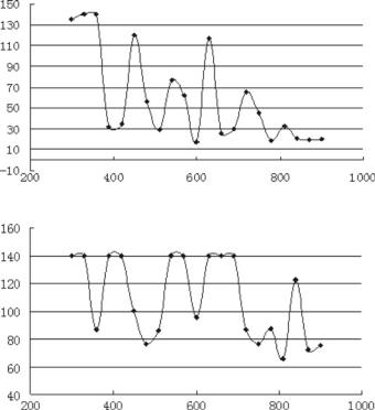
Fig. 8.8 Product susceptibility curve—a RS103 susceptibility curve, b RS103 susceptibility curve when the sensors and cables were covered by the copper mesh
be preliminarily determined that the sensor of the product, the transmission cable, and the connection portion between the two were the main paths for picking up electromagnetic energy, thereby causing the RS103 to fail. Figure 8.8a, b shows the RS103 susceptibility curves for the equipment before and after using the copper mesh. It can be seen from the susceptibility curve that due to the small size of the sensor, the coupling effect on the high-frequency electromagnetic field is strong, and as the frequency increases, the anti-interference ability of the product increases. The electric field intensity that causes susceptibility increases from a minimum of 15 V/m before the copper mesh covering to 64 V/m after the covering.