

2.1 The Theory of Microwave Transmission Line |
41 |
Voltage standing wave ratio and reflection coefficient are used to represent the above three states:
(1)Traveling wave state: |Γ | 0, ρ 1;
(2)Pure standing wave state: |Γ | 1, ρ ∞;
(3)Traveling–standing wave state: 0 < |Γ | < 1, 1 < ρ < ∞.
2.2Application of Transmission Line Theories in EMC Research
The basic ideas and methods of the transmission line theory have a wide range of applications in EMC research. Now, we use the discussion of case shielding effectiveness in Fig. 2.1 as an example, to further explain how the microwave transmission line theory can be applied to EMC problems.
2.2.1Application of the Single-Conductor Transmission Lines in EMC Research
The cutoff frequency characteristic of a single-conductor transmission line has an important guiding significance to improve the shielding effectiveness of the ventilation holes and slits of the case.
1. Shielding design for the ventilation holes
The size of the aperture should be calculated according to the shielding requirements (including the frequency band to be shielded and the shielding requirement) and the wavelength corresponding to the highest frequency to be shielded.
The specific calculation formula is: Suppose the highest frequency that needs to be shielded is fc, the corresponding wavelength is λc, and the diameter of the aperture
cannot be greater than λc 10. For example, if the maximum frequency to be shielded is 10 GHz (the wavelength corresponding to 10 GHz is 3 cm), the diameter of the aperture should not be greater than 3 mm.
2. Shielding design of slots
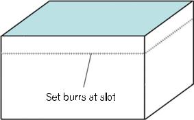
The slot generally has a characteristic that it is narrow in one direction and long in the perpendicular direction. The problem of decreasing cutoff frequency caused by the long slots must be considered. The specific solution is to set “glitches” that meet the cutoff requirements along the longest direction according to the highest frequency that needs to be cut off, so that the long slots are cut into short slits as shown in Fig. 2.7.
In the shielding design of the aperture and slot, in addition to the relationship between the aperture size and the cutoff wavelength, it is also necessary to consider
42 |
2 Microwave Technology |
Fig. 2.7 Set a glitch at the long slot
the attenuation path length of the withering mode, that is, the wall thickness of the aperture and the slot.
When the shielding requirement is high, the following measures can be taken to improve the shielding effect:
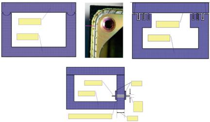
Concave–convex design at the joint between the case and the cover to increase the cutoff length of the withering mode as shown in Fig. 2.8a;
Reed design at the joint between the case and the cover to convert the long slot into short slots as shown in Fig. 2.8b;
Flange design at the joint between the case and the cover to increase the cutoff length of the withering mode as shown in Fig. 2.8c;
The cable passes through box which can be equivalent to the double-conductor transmission line effect, as shown in Fig. 2.8d.
2.2.2Application of Multi-conductor Transmission Lines in EMC
The shield design of the keyboard, buttons, switches, power lines, and data lines of the case in Fig. 2.1 needs to refer to the characteristics of the double-conductor and multi-conductor transmission line.
Shielding design of the above units exploits the basic principles of the doubleconductor or multi-conductor transmission line as shown in Fig. 2.8d. The factors that affect the shielding effectiveness include:
(1)The aperture size of the cable passing through the case. We should try to enable the closed case with shielding capacity, so the aperture of the through-wall should be as small as possible.
2.2 Application of Transmission Line Theories in EMC Research |
43 |
||
(a) |
(b) |
(c) |
|
|
Case cover |
|
Case cover |
|
|
|
|
|
Case body |
|
Case body |
(d)
Cable through wall |
Filter |
Case body
Throughwall aperture
360 degree jonit over the connector and the case |
Wall |
|
thickness |
Fig. 2.8 Design to improve the shielding effectiveness of the case. a Concave–convex design at the joint between the case and the cover; b reed design at the joint between the case and the cover; c flange design at the joint between the case and the cover; and d the cable passes through the box
(2)The thickness of the case wall. Appropriately increase the thickness of the case wall where the cable passes through, so that the cavity may have some contribution to the shielding.
(3)The through-wall connector which electrically connects to the case in 360°. The through-wall cable makes it possible that the electromagnetic energy from the DC may overflow the wall. Therefore, the connector and the case connecting in 360° can effectively ensure the overall electrical continuity of the case.
(4)A connector with filtering capability. The double-conductor effect makes it possible for all frequency signals starting from DC to leak. Therefore, only the useful frequency signal carried by the through-wall signal line is allowed to pass, and the signal amplitude of other frequencies is effectively attenuated by the filter to improve the shielding effectiveness of the case.