

90 |
|
4 Basic Concepts of Quantitative System-Level EMC Design |
|||||||||||||
|
|
|
|
|
|
|
|
|
|
|
|
|
|
|
|
|
|
|
|
|
|
|
|
|
|
|
|
|
|
|
|
|
|
|
|
|
|
|
|
|
|
|
|
|
|
|
|
|
|
|
|
|
|
|
|
|
|
|
|
|
|
|
|
|
|
|
|
|
|
|
|
|
|
|
|
|
|
|
|
|
|
|
|
|
|
|
|
|
|
|
|
|
|
|
|
|
|
|
|
|
|
|
|
|
|
|
|
|
|
|
|
|
|
|
|
|
|
|
|
|
|
|
|
|
|
|
|
|
|
|
|
|
|
|
|
|
|
|
|
|
|
|
|
|
|
|
|
|
|
|
|
|
|
|
|
|
|
|
|
|
|
|
|
|
|
|
|
|
|
|
|
|
|
|
|
|
|
|
|
|
|
|
|
|
|
|
|
|
|
|
|
|
|
|
|
|
|
|
|
|
|
|
|
|
|
|
|
|
|
|
|
|
|
|
|
|
|
|
|
|
|
|
|
|
|
|
|
|
|
|
|
|
|
|
|
|
|
|
|
|
|
|
|
|
|
|
|
|
|
|
|
|
|
|
|
|
|
|
|
|
|
|
|
|
|
|
|
|
|
|
|
|
|
|
|
|
|
|
|
|
|
|
|
|
|
|
|
|
|
|
|
|
|
|
|
|
|
|
|
|
|
|
|
|
|
|
|
|
|
|
|
|
|
|
|
|
|
|
|
|
|
|
|
|
|
|
|
|
|
|
|
|
|
|
|
|
|
|
|
|
|
|
|
|
|
|
|
|
|
|
|
|
|
|
|
|
|
|
|
|
|
|
|
|
|
|
|
|
|
|
|
|
|
|
|
|
|
|
|
|
|
|
|
|
|
|
|
|
|
|
|
|
|
|
|
|
|
|
|
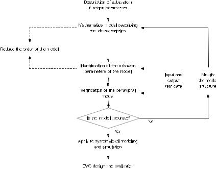
Fig. 4.17 Flowchart of EMC behavioral modeling and simulation
there are not only circuit-level problems, but also a large number of electromagnetic field coupling problems. Therefore, in the behavioral model, the influence of the electromagnetic field must be considered. In other words, to build an accurate behavioral model, we need to reform the field information (including near-field, farfield, and transition zone), the field–circuit coupling, and the distribution effect of the circuit–circuit parameter to the interference source at the circuit level.
Based on the EMC behavioral model, we can establish an EMC model of the whole aircraft that can be used in the simulation. The model is referred to as an aircraft EMC digital model. Based on the digital model of aircraft EMC, we can further carry out electromagnetic emission characteristics prediction and control, electromagnetic susceptibility characteristics prediction and protection design, and electromagnetic vulnerability prediction, etc.
4.3.8 The Behavior Simulation of EMC
EMC behavioral simulation technology is proposed as a key to solve the EMC quantitative demonstration and design from the top level of the system.
4.3 Basic Concept of EMC Quantitative Design |
91 |
The behavioral model makes it possible to quantitatively demonstrate and design EMC of the system. It provides the necessary technical foundation for EMC from conceptual design to detailed design and lays the foundation for EMC behavioral simulation. Behavioral simulation method refers to the analysis of system characteristics and the external responses based on the behavioral model of the system.
EMC behavioral simulation: According to the EME where the system operates, the EMI signal and the functional signal are commonly equivalent to the input signal of the behavioral simulation, and based on the EMC behavioral model of the system and subsystem/equipment, the system performance can be simulated.
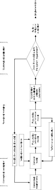
Figure 4.18 shows the process of behavioral modeling, model verification, and behavioral simulation analysis. It includes the following three stages.
(1)Stage of concept description: In the initial stage of system design, the concept and requirements of the system are proposed, a conceptual model is established, and the key attributes of the system are analyzed.
(2)Stage of behavioral modeling: An executable behavioral model of system functions is constructed. Then, we quantify the conceptual model established in the first stage and use a formal modeling language and modeling tools to create an executable abstract model. As a result, the functional properties of the system based on the execution of the model can be analyzed.
(3)Stage of system-level application: The behavioral model is extended to executable performance analysis model based on performance analysis. The performance of the system is then analyzed quantitatively according to the result of simulated execution of the model. Then, we can determine whether the functional attributes of the system meet the system requirements and apply the analysis to practice.
4.3.9Quantitative Modeling Based on EMC Gray System Theory
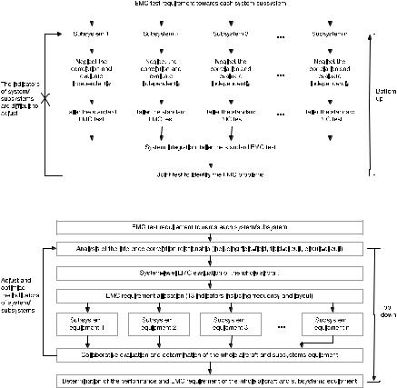
When the relationship between the input and output of the system is available, we can build EMC behavioral model at system level and subsystem/equipment level (EMC information can be extracted from test data during the development stage, and the model can be further revised).
However, in many cases, the key input and output parameters of some equipment in the system are unavailable, which makes it difficult to establish an EMC behavioral model. In order to obtain the key input and output parameters of the equipment, the EMC characteristics of some equipment, such as the harmonic interference characteristics and the noise spectrum of the power supply, can be extracted through testing. Then, we can summarize the characteristics and derive regular formulas to build analytical model of equipment/module with incomplete design parameters. This is the EMC quantitative modeling method proposed by the EMC research team of Beihang University [15]. By using gray theory [17, 18], the different interference factors
92 |
4 Basic Concepts of Quantitative System-Level EMC Design |
|||||
|
|
|
|
|
|
|
|
|
|
|
|
|
|
|
|
|
|
|
|
|
|
|
|
|
|
|
|
|
|
|
|
|
|
|
Fig. 4.18 Process of behavioral modeling, model verification, and behavioral simulation analysis
4.3 Basic Concept of EMC Quantitative Design |
93 |
in the same equipment interference spectrum are analyzed and different harmonic interference and broadband interference of the equipment are identified based on the test data. Thus, we can establish a gray model by summarizing the emission of the equipment. Finally, we can achieve better accuracy with small testing data using the best accurate modeling method for equipment under the least square criterion.
The EMC modeling method based on gray system theory can be used to model the EMC of systems with incomplete information, thus effectively solving the problem of equipment’s EMC simulation analysis and improving the accuracy of system-level EMC research.

Chapter 5
Critical Techniques of Quantitative
System-Level EMC Design
The proposed quantification system-level EMC design is a top-down process. It translates the overall EMC requirements proposed in the demonstration phases into the overall EMC technical requirements, and further decomposes it into requirements for subsystems and equipment. Thus, the EMC design of system and subsystem/equipment can be implemented in the scheme phase. Then, EMC evaluation, design adjustment, performance control, and verification are conducted during the engineering development phase. Finally, the process control requirements during the production phase for EMC design and the requirements for EMC maintenance during the application phase are carried out. With this method, the advanced principle of EMC in a process from conceptual design to detailed design and finally to physical design can be achieved, through which we make continuous adjustment to achieve the optimal performance.
Quantitative system-level EMC design is a brand-new technology that incorporates multi-disciplinary knowledge including system engineering theory, electromagnetic field theory, communication theory, control theory, reliability, and theory. The advancement of this technology lies in the usage of predesign instead of postvalidation, and quantitative design instead of experience-based design.
The conventional workflow of EMC design is shown in Fig. 5.1. The overall EMC requirements made by the project manager to the subsystems/equipment are mainly the test items specified by the EMC regulations, and there is little difference for a different subsystem/equipment. In this situation, if there is not enough information for subsystem/equipment about the EME where it operates, and no analysis on the requirements of the EMC test items, there will hardly be any design aiming at passing the EMC regulation test during the scheme design of subsystems/equipment. As a result, when the engineering prototype went through the EMC tests, items such as RE102, CE102, RS103, CS101, and CS114 are difficult to pass. Until now, the common method for EMC design is still to solve the problem only after it is exposed in the later phase of the development.
The root causes of a large number of EMC problems in the later phases are: (1) no top-level design of EMC in the early phase of system design; (2) no quality control
© National Defense Industry Press and Springer Nature Singapore Pte Ltd. 2019 |
95 |
D. Su et al., Theory and Methods of Quantification Design on System-Level Electromagnetic Compatibility, https://doi.org/10.1007/978-981-13-3690-4_5
96 |
|
|
5 Critical Techniques of Quantitative System-Level EMC Design |
||||||||||||
|
|
|
|
|
|
|
|
|
|
|
|
|
|
|
|
|
|
|
|
|
|
|
|
|
|
|
|
|
|
|
|
|
|
|
|
|
|
|
|
|
|
|
|
|
|
|
|
|
|
|
|
|
|
|
|
|
|
|
|
|
|
|
|
|
|
|
|
|
|
|
|
|
|
|
|
|
|
|
|
|
|
|
|
|
|
|
|
|
|
|
|
|
|
|
|
|
|
|
|
|
|
|
|
|
|
|
|
|
|
|
|
|
|
|
|
|
|
|
|
|
|
|
|
|
|
|
|
|
|
|
|
|
|
|
|
|
|
|
|
|
|
|
|
|
|
|
|
|
|
|
|
|
|
|
|
|
|
|
|
|
|
|
|
|
|
|
|
|
|
|
|
|
|
|
|
|
|
|
|
|
|
|
|
|
|
|
|
|
|
|
|
|
|
|
|
|
|
|
|
|
|
|
|
|
|
|
|
|
|
|
|
|
|
|
|
|
|
|
|
|
|
|
|
|
|
|
|
|
|
|
|
|
|
|
|
|
|
|
|
|
|
|
|
|
|
|
|
|
|
|
|
|
|
|
|
|
|
|
|
|
|
|
|
|
|
|
|
|
|
|
|
|
|
|
|
|
|
|
|
|
|
|
|
|
|
|
|
|
|
|
|
|
|
|
|
|
|
|
|
|
|
|
|
|
|
|
|
|
|
|
|
|
|
|
|
|
|
|
|
Fig. 5.1 Conventional EMC design process
Fig. 5.2 Process of quantitative system-level EMC design
of EMC in the development process; and (3) no standard methods at industrial level for EMC demonstration and design.
Aircraft is used as an example to discuss the quantitative system-level EMC design and introduce the design methods as shown in Fig. 5.2.
5.1Principles, Methods, and Workflow for Quantitative System-Level EMC Design
To begin with, we will introduce the basic principles of quantitative system-level EMC design. First, the system is considered as a complex system with multi- input/multi-output ports, an internal multilayer/multi-node/multi-directional coupling relationship, and frequency–time–space–code–polarization response charac-
5.1 Principles, Methods, and Workflow for Quantitative System-Level EMC Design |
97 |
teristic. Second, the functional/nonfunctional field coupling relationships and circuit coupling relationship are classified into different levels, and the responses are classified into linear and nonlinear responses. Then based on the basic principle of the system, and according to the equivalent model of the input and output ports, an equivalent behavioral model of the system can be built. Thirdly, the tactical and technical requirements, functional requirements, EME requirements, and EMC requirements are taken as input of the quantitative and collaborative design methods, which also takes the system and subsystem/equipment functions into consideration. As a result, the system and subsystems/equipment can work together and the incompatible working status can be warned in advance.
According to the structure and shape (data provided by CATIA, UG, Pro-E, etc.) of the aircraft and the structure and relative layout of the installed subsystems/equipment (including electronic equipment, airborne antennas, and cables), the design principles of onboard electronics system, input and output port characteristics, and electrical characteristic pretest data, we can establish the EMC digital model of the aircraft (EMC digital prototype of the aircraft), and EMC behavioral simulation model of the airborne electronic systems and mission electronic systems. According to the operating bandwidth, receiver sensitivity, polarization characteristics, signal characteristics, nonlinear characteristics of RF front-end, receiving antenna characteristics, transmitting power, spurious emission characteristics, transmitting antenna characteristics, possible layout on the aircraft, and the attenuation characteristics of the connection cables, the EMI relationship matrix of airborne/mission electronic systems and equipment can be obtained using field–circuit coupling co-analysis method. Then, the EMC safety of the airborne electronic subsystems can be classified based on the electromagnetic emission and susceptive characteristics of airborne electronic systems. Thus, EMC prediction of the aircraft, establishment of top-level EMC indicators, decomposition of subsystem EMC indicators, quantitative evaluation, and control of the aircraft EMC can be achieved. After completing the above work, the desired EMC performance of the aircraft can be ultimately satisfied.
Now, we explain the detailed method of quantitative system-level EMC design. As an important support for the development of aircraft, the first step in systemlevel EMC design is to conduct EMC evaluation on the preliminary design scheme of the aircraft. The evaluation includes the rationality of the antenna layout, equipment layout, cable layout, the selection of equipment indicators, and the electromagnetic safety of the whole aircraft. Based on the result of the evaluation, electromagnetic incompatibility problems will be discovered. Then, the overall EMC technical requirements of the whole aircraft can be proposed in accordance with the overall EMC requirement for the aircraft, including the design indicator requirements and test requirements. Next, the overall technical requirements can be decomposed to subsystems and equipment.
A large number of electronic information systems are usually installed on an aircraft. Therefore, it is necessary to identify all electromagnetic emission sources and susceptive equipment of interest in order to establish an interference relationship before evaluation. Then, we can analyze the possible energy transmission channel between the electromagnetic emission sources and susceptive equipment in the form
98 |
5 Critical Techniques of Quantitative System-Level EMC Design |
of field–field, field–circuit, and circuit–circuit. Thus, we can construct an interference correlation matrix of the whole aircraft and evaluate the EMC based on the quantitative results given by the interference correlation matrix. Layout or indicator adjustments are then performed on equipment that do not meet the compatibility requirements in the interference correlation matrix. Finally, the key parameters of EMC design that satisfy the EMC requirements of the whole aircraft can be obtained. The key parameters include: the frequency coordination relationship between the transmitters and receivers; the isolation between the electromagnetic emission source and the susceptive equipment; the layout of antennas, equipment, and cables; the EME characteristics of the key parts inside and outside the cabin; the energy matching requirements between the transmitters and the receivers (i.e., transmission power, out-of-band attenuation of transmitters, receiving sensitivity, out-of-band suppression of receivers, signal-to-noise ratio required for properly receiving), cabin shielding and resonance characteristics; tolerable degradation of equipment; equipment safety priorities; and safety margins for susceptive equipment.
Figure 5.3 illustrates the design and evaluation process for the quantitative systemlevel EMC design. The EMC geometric model of the aircraft is built based on the geometric model for engineering design (e.g., CATIA model, UG model, Pro-E model) Then, the EME inside and outside the cabin, the shielding effectiveness, and the resonance characteristics of the aircraft cabin are simulated based on the emission equipment and its antenna parameters, antenna layout characteristics, etc. Thus, the interference correlation matrix at the operator’s position, fuel tank, etc., can be constructed and its electromagnetic security can be analyzed. Meanwhile, using the system model based on electromagnetic field method, a field–circuit coupling model based on distribution effects, a behavioral simulation model based on the circuit method [19], the isolation between transmitting antennas and receiving antennas, and the coupling between transmitters and receivers can be calculated. Furthermore, the safety of the equipment can be analyzed using the interference correlation matrix of the susceptive equipment.
According to the results of EMC evaluation, the overall technical requirements (with amendments to the indicators of the preliminary design scheme) for EMC of the whole aircraft can be proposed, and the overall technical requirements for EMC of the whole aircraft can be quantitatively allocated to subsystems and equipment. The subsystem/equipment is designed according to the technical requirements proposed by the whole aircraft. Therefore, the subsystem/equipment scheme needs to be evaluated in conjunction with the aircraft’s overall design scheme and the design is subject to adjustment based on the evaluation results. EMC tests can also be conducted when necessary.
Here, we summarize the major steps of quantitative design of system-level EMC.
(1) Develop the top-level technical indicators for system EMC; (2) develop EMC technical indicators for subsystem/equipment; (3) conduct subsystem/equipment’s EMC design, and predict its impact on the EMC of the whole aircraft; (4) conduct collaborative design of EMC of subsystems/equipment and systems, and optimize subsystem/equipment’s EMC indicators; (5) conduct subsystem/equipment’s EMC tests, and improve the EMC design of subsystem/equipment based on the test results;