

78 |
4 Basic Concepts of Quantitative System-Level EMC Design |
|
Table 4.1 Difference between EMI in EMC and jamming in electronic warfare |
||
|
|
|
EMI |
|
Jamming |
|
|
|
Intentional |
|
Unintentional |
|
|
|
Emission |
|
Transmission |
|
|
|
Susceptive |
|
Damage |
|
|
|
Table 4.2 Technical domain attributions of common interference phenomena
Type of disturbance source |
Type of disturbance |
Classification of subjects |
|
|
|
Self-interference in our |
Unintentional interference |
EMC |
system |
|
|
|
|
|
Inter-interference in our |
Unintentional interference |
EMC/E3 |
system |
|
|
|
|
|
Interference in our civil |
Unintentional interference |
EMC/E3 |
environment |
|
|
|
|
|
Interference from our |
Unintentional interference |
EMC/E3 |
equipment in the battlefield |
|
|
|
|
|
Interference from enemy |
Unintentional interference |
EMC/E3 |
equipment in the battlefield |
|
|
|
|
|
Intentional interference from |
Intentional interference |
Electronic warfare |
enemy equipment in the |
|
|
battlefield |
|
|
|
|
|
4.2.5 Interpretations of the EMI in Different Fields
There are different interpretations of EMI in different fields. In the field of EMC, interference refers to the phenomenon of unintentional signal generation. In the field of electronic warfare, interference generally corresponds to intentional interference. Due to the different technologies adopted in the two cases, to avoid confusion, the interference in the field of EMC is still called EMI, and the interference in electronic warfare is called jamming, as listed in Table 4.1.
Table 4.2 lists the technical domain attributions of common interference phenomena (attribution is not unique and is subject to change).
4.3 Basic Concept of EMC Quantitative Design
4.3.1 Interference Correlation Relationship
The mutual interference among the subsystems and equipment in the system is called the interference relationship. It is usually obtained based on the analysis of the energy coupling relationships among the equipment in the system, which requires to con-

4.3 Basic Concept of EMC Quantitative Design |
79 |
|||||||||||||||||||||
|
|
|
|
|
|
|
|
|
|
|
|
|
|
|
|
|
|
|
|
|
|
|
|
|
|
|
|
|
|
|
|
|
|
|
|
|
|
|
|
|
|
|
|
|
|
|
|
|
|
|
|
|
|
|
|
|
|
|
|
|
|
|
|
|
|
|
|
|
|
|
|
|
|
|
|
|
|
|
|
|
|
|
|
|
|
|
|
|
|
|
|
|
|
|
|
|
|
|
|
|
|
|
|
|
|
|
|
|
|
|
|
|
|
|
|
|
|
|
|
|
|
|
|
|
|
|
|
|
|
|
|
|
|
|
|
|
|
|
|
|
|
|
|
|
|
|
|
|
|
|
|
|
|
|
|
|
|
|
|
|
|
|
|
|
|
|
|
|
|
|
|
|
|
|
|
|
|
|
|
|
|
|
|
|
|
|
|
|
|
|
|
|
|
|
|
|
|
|
|
|
|
|
|
|
|
|
|
|
|
|
|
|
|
|
|
|
|
|
|
|
|
|
|
|
|
|
|
|
|
Fig. 4.11 Interference relationships among some airborne equipment
sider not only the energy coupling generated by the antenna of the transmitter and receiver, but also the energy coupling caused by the cases, cables, connectors, and even the power supply and grounding. Since the electromagnetic energy coupling in large-scale systems is usually complex, when analyzing interference relationships, a hierarchical analysis approach should be adopted; i.e., the energy coupling generated by the antenna of the transceiver system is considered firstly, then the coupling generated by cables and cases is considered, and finally, grounding and other couplings are considered. Figure 4.11 shows the interference relationships between some of the aircraft’s airborne equipment. The interference relationships can also be expressed in tabular form.
In general, an aircraft includes transmitting equipment that radiates through antenna ports and other radiation equipment, as well as susceptive equipment that receivers coupled through antenna ports and other susceptive equipment. The interference correlation relationship within the entire system is complex, and the number of equipment is large. Figure 4.11 only describes the partial interference correlation relationship of the onboard equipment including communications, radar, altimeter, TACAN, and weather radar through the antenna port. In fact, when analyzing and evaluating EMC of the whole system, the number of radiation source ports and the number of susceptive ports are even bigger, and the coupling is more complicated.
4.3.2 Interference Correlation Matrix
The mathematical model to describe the interference correlation relationship quantitatively is called the interference correlation matrix. The matrix can reflect the mutual interference relationship of the whole aircraft system in a comprehensive, clear, and accurate manner [13]. It provides an important technical method for analyzing, eval-
80 |
4 Basic Concepts of Quantitative System-Level EMC Design |
uating, and optimizing the EMC of the whole aircraft and can be used to allocate the EMC indicators of the whole aircraft to subsystems/equipment.
The interference correlation matrix includes multiple forms, such as the coupling interference correlation matrix, isolation interference correlation matrix, and impedance interference correlation matrix. It depends on the specific analysis requirements to decide which type of matrix to use.
Equation (4.1) describes the coupling interference matrix (A) of a steady-state system. There are M interference ports and N susceptive ports in the system. The coupling function between the j-th susceptive port and the i-th interference port is
Hi, j (t, f ):
|
|
|
. |
· · · |
|
. |
· · · |
|
. |
|
|
|
H1,1(t, f ) |
|
H1, j (t, f ) |
|
H1,N (t, f ) |
|
|||||
|
|
|
. |
|
|
. |
|
|
. |
|
|
|
|
. |
|
|
. |
|
|
. |
|
||
A |
|
|
|
|
|
|
|
|
|
|
|
|
H |
(t, f ) |
· · · |
H |
(t, f ) |
· · · |
H |
(t, f ) |
|
(4.1) |
|
|
|
i,1 |
. |
i, j |
. |
i,N |
. |
|
|
||
|
|
|
|
|
|
|
|
|
|||
|
|
|
. |
|
|
. |
|
|
. |
|
|
|
|
|
. |
|
|
. |
|
|
. |
|
|
HM,1(t, f ) · · · HM, j (t, f ) · · · HM,N (t, f )
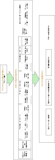
4.3.3 System-Level EMC Requirements and Indicators
1. System-level EMC requirements
System-level EMC requirements include three aspects: the overall EMC requirements, the overall EMC technical requirements, and the EMC management requirements.
The overall EMC requirements are usually clearly stated in the general requirements for product development and are defined in terms of use. When making the overall EMC requirements for a product, comprehensive consideration must be given to the natural or man-made EME where the product operates, the electromagnetic emission occurs when the product is in operation, the electromagnetic susceptibility that affects the function of the product, the EMC problems happened to the product before, and the requirements and methods for EMC evaluation of the product, etc.
The overall EMC technical requirements are based on the technical aspects of the overall requirements and are generally specified in the overall development plan. When making the overall EMC technical requirements, natural and man-made EME where the products operates, the electromagnetic emission generated by the product while in operation, the electromagnetic susceptibility affecting the function of the product, etc., need to be provided quantitatively. For example, the electric field intensity and magnetic field intensity corresponding to the EME, the time-domain feature of the transient field, the spectrum occupancy of the frequency-domain signal, and the characteristics of the pulse signal need to be provided. The overall technical EMC requirements should be based on the hierarchical levels of the system, subsystems, and equipment. The limits of the product’s EMC test should also be specified.
4.3 Basic Concept of EMC Quantitative Design |
81 |
EMC management puts forward requirements from the perspective of quality and standardization. It is usually specified in the overall development requirements. EMC management commonly includes the operating mechanism, management content, and control measures (milestones, control content, evaluation elements) of the product.
2. System-level EMC indicators
System-level EMC indicators consist of three items: demonstration indicator, design indicator, and test indicator. The demonstration indicator is used to control the overall EMC performance of the product. The design indicator is derived from the demonstration indicator. It is not only the input indicator of the system’s EMC design, but can also be developed into the system’s EMC test indicator. The test indicator specifies the EMC limit requirement of the system. It is used to test whether the EMC design of the system is effective and whether the actual EMC performance of the system meets the requirements of the EMC demonstration indicator. The relationship among the three indicators is shown in Fig. 4.12.
(1) Demonstration indicators
Finding indicators that objectively reflect the overall EMC of a product is a topic that needs continuous research. The EMC research team of Beihang University has investigated this issue for more than 10 years and has obtained preliminary research results—the EMC condition (EMC(s)) that characterize the EMC of the whole aircraft at system level [12]. EMC(s) quantitatively describes EMC of the system, subsystem, or component as a whole. It represents the extent to which the object being analyzed satisfies EMC requirement considering the four major factors including electromagnetic emission, electromagnetic susceptibility, isolation, and safety margin.
When the complete system of the aircraft has been integrated: If all susceptive equipment can work normally according to design specifications, and fuel and personnel safety also meet the requirement, then EMC(s) equals 1. On the other hand, if all susceptive equipment is affected by interference, fuel and personnel are exposed to radiation that exceeds the standard, then EMC(s) equals 0. In engineering practice, generally 0 < EMC(s) ≤ 1. The purpose of establishing the indicator for EMC condition in the demonstration phase is to control the overall EMC level of the aircraft. The purpose of EMC design and optimization is to make EMC(s) close to or equal to 1.
(2) Design indicators
The EMC design indicator has a close relationship with the system design indicator. It specifies system requirements from the perspective of EMC. EMC design indicators have eight categories, i.e., frequency resource planning, EME, transmitter performance (transmitting frequency, transmitting power, harmonic suppression, out-of- band suppression), receiver performance (receiving frequency, receiving sensitivity, adjacent channel suppression, out-of-band suppression), antenna layout performance (antenna pattern, polarization, antenna isolation, suppression capabilities), equipment and cable layout, interconnection characteristics (frequency band coupling, shielding effectiveness, power and grounding), and damage threshold.
82 |
4 Basic Concepts of Quantitative System-Level EMC Design |
|||||
|
|
|
|
|
|
|
|
|
|
|
|
|
|
|
|
|
|
|
|
|
|
|
|
|
|
|
|
|
|
|
|
|
|
|
|
|
|
|
|
|
|
|
|
|
|
|
|
|
|
|
|
|
|
|
|
|
|
|
|
|
|
|
Fig. 4.12 Relationship among EMC demonstration indicators, design indicators, and test indicators
4.3 Basic Concept of EMC Quantitative Design |
83 |
The frequency resource planning, EME, antenna layout, equipment and cable layout, interconnection characteristics, and damage threshold are indicators directly associated with the system-level design and are generally designed and controlled by the project manager. The corresponding control parameters are isolation and safety margin. Transmitter and receiver performance is based on the overall system isolation and safety margin requirements, which need to be determined in close consultation with the transmitting equipment, receiving equipment, and subsystems. The corresponding control parameters are directly related to the performance of the transmitting/receiving equipment.
Among the eight categories of design indicators we just introduced, EME and transmitter performance are the “sources” of the EMI profile. Receiver performance is an important factor in determining susceptibility profiles. Frequency resource planning, antenna layout performance, equipment and cable layout, and interconnection characteristics are important ways to avoid the susceptibility profile and the interference profile reaching each other. And the damage threshold is an important basis to determine the safety margin.
For large-scale systems with dozens or even hundreds of equipment and subsystems such as airplanes, in order to formulate the design indicators for the system, subsystem, and equipment, it usually requires EMC models and EMC simulation methods.
(3) Test indicators
EMC test requirements come in system level and equipment/subsystem level. GJB 1389 sets out detailed requirements for system-level EMC, while GJB 151 sets out requirements for equipment/subsystems and provides test methods in detail.
According to the three aspects of EMC, the EMC evaluation test requirements include conduction emission (CE), conduction susceptibility (CS), radiation emission (RE), and radiation susceptibility (RS). The requirements apply to both the system-level test and the subsystem-/equipment-level test. Conduction emission and radiation emission are two types of tests to evaluate the product’s external electromagnetic emission characteristics. In these tests, the product is subject to the investigation as the “interference source.” On the other hand, the conduction and radiation susceptive tests evaluate the product’s characteristics of being interfered by external electromagnetic signals. In these tests, the product is treated as a “susceptive object.” Sometimes, the same product can be both the “interference source” and the “susceptive object.” The product’s own antenna, cable, case, and reference ground can serve as the “interference sources” to other products. At the same time, the product can also be interfered by others and become the “susceptive object.”
System-level EMC test requirements include safety margin, intra-system EMC, external RF EME, lightning, electromagnetic pulse (EMP), subsystems and equipment EMI, electrostatic charge control, electromagnetic radiation hazards (EMRADHAZ), and E3 hardness in the life cycle, electrical bonding, external grounds, TEMPEST, emission control (EMCON), and EM spectrum compatibility.
84 |
4 Basic Concepts of Quantitative System-Level EMC Design |
|
|
Electromagnetic Emission |
Electromagnetic Susceptibility |
Sensitive Profile
not smaller than
the limit requirements
of electromagntic
susceptibility
Safety Margin
Limit of Electromagnetic
Emission
Vulnerable Points
Leakage Profile
not bigger than
the limit requirements of electromagntic susceptibility
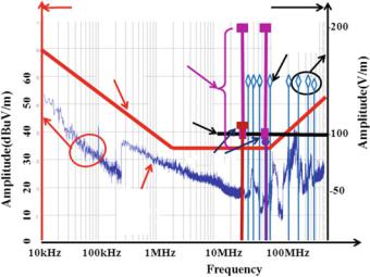
Fig. 4.13 Relationships among electromagnetic emission profile, electromagnetic susceptibility profile, vulnerable points, and safety margin
4.3.4Electromagnetic Emission Profile and Electromagnetic Susceptibility Profile
The amplitude–frequency characteristic of the product’s electromagnetic emission is called the electromagnetic emission profile. The product’s amplitude–frequency characteristic of electromagnetic susceptibility is called the electromagnetically susceptibility profile, as shown in Fig. 4.13.
In Fig. 4.13, the solid line using the left axis as the vertical axis is the electromagnetic emission profile. The dotted line with ♦ using the right axis as the vertical axis is the electromagnetic susceptibility profile. Points marked with are the vulnerable points. Points marked with ♦ are electromagnetic susceptive points and their corresponding threshold. The thick line between ♦ and is the magnitude corresponding to the electromagnetic safety margin. And the difference between electromagnetic susceptibility profile that satisfies the limit requirements (needs to consider the safety margin at the vulnerable points) and the electromagnetic emission profile is the degree of isolation.
Product isolation requirement can be derived based on the analysis of product emission profile and susceptibility profile. Safety margin requirement can be further determined for the vulnerable points. Electromagnetic emission profile, electromagnetic susceptibility profile, isolation, and safety margins reflect the interrelationship of the three aspects of EMC: Electromagnetic emission profile is an objective reflection of unintentional emission of the product and describes the electromagnetic emission generated by the emission sources; the electromagnetic susceptibility