

54 |
3 Antenna Theory and Engineering |
3.2.6 Antenna Feed System
This section will introduce the concept of the antenna feed system. Through this section, our readers will understand that antenna isolation is only one of the many important tasks in analyzing system-level EMC problems. To design the EMC of the whole aircraft, it is also necessary to grasp the RF front-end characteristics of the antenna feed system and analyze the isolation between the equipment besides antenna isolation.
The antenna system of a typical radio application system consists of a feed network and an antenna. To improve the receiving sensitivity, a low-noise amplifier (LNA) is sometimes used to connect to the receiving antenna. Since antennas are both the transmitting and receiving ports of the electromagnetic energy in communication electronic equipment, they are most likely to form mutual radiation interference. In other words, electronic systems are highly possible to couple to each other through antennas. Therefore, how to achieve high isolation between antennas becomes the key to achieve compatibility between electronic equipment.
1. Input impedance and antenna matching
The input impedance of antenna is the impedance presented by the input of the antenna, that is, the ratio of the input voltage to the current at the antenna feed end. The input impedance of the antenna is affected by other antennas and adjacent objects. It consists of real and imaginary parts as
Zin Rin + j Xin |
(3.4) |
where the input resistance (Rin ) represents power loss. The power can be consumed in two ways, namely radiated out in the form of electromagnetic waves and heat loss from the antenna. Input reactance Xin indicates the storage of the power in the near field of the antenna.
The best scenario connection between the antenna and the feed is that the input impedance of the antenna is pure resistance and is equal to the characteristic impedance of the feed. Under this condition, there is no power reflection at the feed port, and there is no standing wave on the feed. The input impedance of the antenna changes gently with frequency. The feeding network is used to complete the matching work of the antenna, eliminate the reactance component in the input impedance, and make the resistance component as close as possible to the characteristic impedance of the feed. The input impedance of the general communication and radar antenna is 50 .
The quality of antenna matching can be measured by parameters such as reflection coefficient, traveling wave ratio, standing wave ratio (SWR) and return loss. There is a certain numerical relationship between these four parameters. In general, SWR and return loss are used frequently.

3.2 Basic Antenna Concepts |
55 |
2. Return loss
The return loss is the reciprocal of the absolute value of the reflection coefficient and it is expressed in decibels. The value of the return loss is between 0 dB and infinity. The smaller the return loss, the worse the match and vice versa. 0 dB means total reflection, and on the contrary, infinity means complete match.
3. Voltage standing wave ratio (VSWR)
The impedance of the antenna feed should be exactly matched with the input impedance of the antenna. Otherwise, there will be reflected waves at the antenna port, and there will be electromagnetic waves flowing to the signal source on the feeder. The electromagnetic wave formed by the combination of the reflected wave and the incident wave is called a standing wave, and the ratio of the maximum value to the minimum value of the amplitude of a standing wave signal is called the voltage standing wave ratio (VSWR). It is the reciprocal of the traveling wave coefficient and its value is between 1 and infinity. If the SWR equals to 1, it indicates a perfect match. And if the SWR equals to infinity, it indicates the total reflection, which means a complete mismatch. In the communication system, the SWR is generally required to be less than 2–3. However, the VSWR should be less than 2 in practical applications, because excessive VSWR will decrease the efficiency of the transmitter power and cause increased interference within the system, and further affects system’s performance.
Return Loss 20lg |
V SW R + 1 |
(3.5) |
||
V SW R |
− |
1 |
||
|
|
|
|
|
4. Antenna isolation
The antenna isolation is defined as the ratio of the transmitting power (Pt ) of the transmitting antenna to the receiving power (Pr ) received by the receiving antenna:
L |
Pt |
(3.6) |
Pr |
Typically, in engineering applications, it is expressed in dB:
Pt |
|
|
L 10lg Pr |
(dB) |
(3.7) |
When both antennas are in a far field from each other, their energy coupling is mainly from the radiation field. When the polarization between the transmitting and receiving antennas is not completely matched, the loss due to polarization mismatch also needs to be taken into account. The mismatch loss from circular polarization is about 3–4 dB at both vertical and horizontal direction, and the mismatch loss between vertical polarization and horizontal polarization is about 20–35 dB.
If the antennas cannot be located in their far-field region at the same time, then the mutual interference between the two antennas is not mainly from the radiation field, but is caused by the near-field bound field or the near-field induction field. Since the
56 |
3 Antenna Theory and Engineering |
concept of antenna power gain is established in the far field, Eq. (3.6) is not applicable to near-field antenna isolation analysis. In the near-field case, the system composed of the transmitting and receiving antennas can generally be regarded as a two-port network and the mutual interference performance can be solved by analyzing the scattering matrix of the two-port network.
Part II
Methods and Applications of Quantitative
System-Level EMC Design
Electromagnetic compatibility (EMC) is an important ability of electronic information systems. It is the basis and prerequisite for electromagnetic environment adaptability. It covers the whole life cycle from demonstration and development to application of electronic information systems. It is the bottleneck technology for the informatization of electronic information systems. It is a general support technology which ensures that the electronic information systems adapt to the complex electromagnetic environment. It is also the technological basis to improve the survivability, combat effectiveness, and stability of electronic information systems. In summary, it is a major support technology for electronic information systems and it will keep developing with the advancement of electronic information technology.
In this part, we will discuss the quantitative design of system-level EMC of electronic information systems.
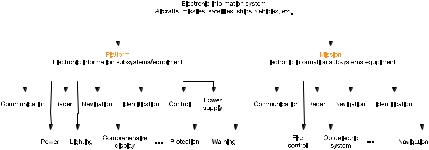
Electronic information systems refer to systems consist of electronic, electrical, electromechanical, and information subsystems/equipment, such as aircrafts, satellites, ships, and vehicles. The electronic information subsystem/equipment is an abbreviation for electronic, electrical, electromechanical, and information subsystems/equipment, including communication, radar, navigation, identification, control, power, and lighting. The electronic information subsystems/equipment can be further classified into subsystems/equipment subordinate to the platform and subsystems/equipment subordinate to the tasks, as shown in Fig. II.1. In this book, the authors use aircraft as an example, but the theory and methods can be adopted by other systems.
The quantitative design of system-level EMC is an important issue related to the development, performance, and security of electronic information systems. The electronic information systems usually have extremely complicated EMC problems due to the system characteristics, such as a wide operating bandwidth, overlapping frequency of transmitting and receiving equipment, large transmitting power of transmitting equipment, high sensitivity of receiving equipment, a large number of antennas, and limited geometric space. In real world, it is also common that the actual electronic information systems have EMC problems caused by the
58 |
|
|
|
|
|
Part II: Methods and Applications of Quantitative System-Level EMC Design |
|||||||||||||||||||||||||||||||||||
|
|
|
|
|
|
|
|
|
|
|
|
|
|
|
|
|
|
|
|
|
|
|
|
|
|
|
|
|
|
|
|
|
|
|
|
|
|
|
|
|
|
|
|
|
|
|
|
|
|
|
|
|
|
|
|
|
|
|
|
|
|
|
|
|
|
|
|
|
|
|
|
|
|
|
|
|
|
|
|
|
|
|
|
|
|
|
|
|
|
|
|
|
|
|
|
|
|
|
|
|
|
|
|
|
|
|
|
|
|
|
|
|
|
|
|
|
|
|
|
|
|
|
|
|
|
|
|
|
|
|
|
|
|
|
|
|
|
|
|
|
|
|
|
|
|
|
|
|
|
|
|
|
|
|
|
|
|
|
|
|
|
|
|
|
|
|
|
|
|
|
|
|
|
|
|
|
|
|
|
|
|
|
|
|
|
|
|
|
|
|
|
|
|
|
|
|
|
|
|
|
|
|
|
|
|
|
|
|
|
|
|
|
|
|
|
|
|
|
|
|
|
|
|
|
|
|
|
|
|
|
|
|
|
|
|
|
|
|
|
|
|
|
|
|
|
|
|
|
|
|
|
|
|
|
|
|
|
|
|
|
|
|
|
|
|
|
|
|
|
|
|
|
|
|
|
|
|
|
|
|
|
|
|
|
|
|
|
|
|
|
|
|
|
|
|
|
|
|
|
|
|
|
|
|
|
|
|
|
|
|
|
|
|
|
|
|
|
|
|
|
|
|
|
|
|
|
|
|
|
|
|
|
|
|
|
|
|
|
|
|
|
|
|
|
|
|
|
|
|
|
|
|
|
|
|
|
|
|
|
|
|
|
|
|
|
|
|
|
|
|
|
|
|
|
|
|
|
|
|
|
|
|
|
|
|
|
|
|
|
|
|
|
|
|
|
|
|
|
|
|
|
|
|
|
|
|
|
|
|
|
|
|
|
|
|
|
|
|
|
|
|
|
|
|
|
|
|
|
|
|
|
|
|
|
|
|
|
|
|
|
|
|
|
|
|
|
|
|
|
|
|
|
|
|
|
|
|
|
|
|
|
|
|
|
|
|
|
|
|
|
|
|
|
|
|
|
|
|
|
|
|
|
|
|
|
|
|
|
|
|
|
|
|
|
|
|
|
|
|
|
|
|
|
|
|
|
|
|
|
|
|
|
|
|
|
|
|
|
|
|
|
|
|
|
|
|
|
|
|
|
|
|
|
|
|
|
|
|
|
|
|
|
|
|
|
Fig. II.1 Classification of electronic information subsystems/equipment
coexistence of new and old electronic information devices, or the coexistence of platform-level and mission-level electronic information devices. Moreover, electronic information systems that contain full-band, high-power transmitting equipment have potential safety issues triggered by high-power transmitting equipment. In addition, most electronic information systems operate in complex and changeable electromagnetic environment. Therefore, EMC is not only an important ability for achieving self-compatibility of electronic information systems, but also an important basis for electronic information systems to obtain the electromagnetic environment adaptability. The compatibility of electronic information systems can be achieved through the quantitative design of system-level EMC.
System-level EMC quantitative design has three key elements: system level, design, and quantification. Specifically, “system level” means that we should work from the perspective of the whole aircraft; “design” should be carried throughout each phase of scheme design—principle prototype design—and engineering prototype design and emphasize each state of conceptual design, digital design, semi-physical design, and physical design; “quantitative” is relative to qualitative and it refers to the quantification of indicators.
Taking aircraft as an example, the difficulties of quantitative design of EMC are mainly as follows:
(1)The aircraft is a electrically large structure (The geometric size of aircrafts can reach several tens of meters. It means that for operating frequencies of 18 GHz or 40 GHz, the aircraft will have a size of several thousand wavelengths or more).
(2)There may be tens of electronic information equipment and antennas installed on the aircraft. The electromagnetic interferences and electronic jamming signals have many different types, which makes the interference correlation relationship of the whole system complex and changeable.
(3)The greatest challenge in quantification during the demonstration, prediction, and design phases is the lack of data. In most cases, only performance data, such as the receiver’s frequency, sensitivity, power, antenna gain, and beam width, can be obtained. The EMC demonstration and design, however, require not only performance data, but also a large amount of nonfunctional data (e.g., the parasitic effect),
Part II: Methods and Applications of Quantitative System-Level EMC Design |
59 |
as well as the correlation between the functional and nonfunctional data. Therefore, the quantification of the whole aircraft’s performance and the EMC performance
indicators is usually carried out under the condition that the subsystems/equipment are almost gray boxes.
This book summarizes the authors’ work for the past 20 years in aircraft EMC analysis, engineering design, and troubleshooting. Taking the aircraft platform, which is a typical electronic information system, as an example, the authors present the issues encountered in the quantitative design of system-level EMC and introduce the method of aircraft EMC design. From the aspects of system-level EMC theory, top-down EMC quantitative design method, and the electromagnetic design of the whole aircraft, the authors describe the quantitative design technology on system-level EMC and the quality control technology in implementation of system-level EMC design, discuss the principal, methodology, and technical measures, and provide the framework of EMC demonstration and design indicator system for the whole aircraft. The authors also present in detail the three-key technologies of quantitative design on system-level EMC, namely the whole digital aircraft system with EMC, behavioral modeling and simulation technology of EMC and field–circuit coupling co-analysis technology. Then, the book introduces the EMC performance control of the whole aircraft and provides design case studies. The methodologies discussed in this book have been proved in applications in various information systems. We hope this book will help our readers in prediction, design, and troubleshooting of the whole lifecycle EMC for electronic information systems.