

Industrial Control (Students guide, 1999, v1.1 )
.pdfExperiment #2: Digital Input Signal Conditioning
Figure 2.7: Slow Response and No Debounce Can be a Problem
Further slowing the execution time of the program loop can help remedy the problem. (If the above program didn’t work properly with StampPlot Lite, a delay in execution speed will allow for serial data transmission). Add a delay of 250 milliseconds to the Action: routine. This allows 250 milliseconds for the switch to settle after closing and then return to its open position.
Modify your program to include “PAUSE 250” to increase the loop time and negate switch bounce.
'Program |
2.3 (modify program 2-2 to slow it down) |
Action: |
' Toggle last state |
TOGGLE |
4 |
TOGGLE |
5 |
PAUSE 250 |
' Added to allow for settling time |
GOTO Loop |
|
Figure 2.8: Adding a Pause Makes the Toggle Challenge Much Easier
By allowing settling time and pressing the button quickly, you make it much easier to get the Action: to occur only once. This technique helps debounce the switch and gives you enough time to release it before the next program cycle. The PAUSE must be long enough to allow for these factors. If the PAUSE is too long, however, a switch closure may occur and never be seen.
Industrial Control Version 1.1 •Page 39

Experiment #2: Digital Input Signal Conditioning
Exercise #3 – Edge Triggering
Counting routines pose additional problems for digital input programming. Exercise #2 used the PAUSE command to eliminate switch bounce, which is compounded in industrial applications such as counting products on a conveyor. Not only does the switch have inherent bounce, but the product itself may have irregular shape, be wobbling, or stop for some time while activating the switch. There may be only one product, but the switch may open and close several times. Also, if the one product stays in contact with the switch for several program loop cycles, the program still should register it only once, not continually like in Program 2.2.
Program 2.4 uses a flag variable to create a program that responds to the initial low-to-high transitions of the switch. Once this “leading edge” of the digital input is detected, Action: will be executed. Then the flag will be set to prevent subsequent executions until the product has cleared and the switch goes low again. Enter Program 2.4.
'Program 2.4: Switch Edge Detection
'Count and display the number of closures of PB1.
'Reset total count with a closure of PB2.
PAUSE 500
DEBUG "!TITL Counting Challenge",CR DEBUG "!TMAX 50",CR
DEBUG "!PNTS 300",CR
DEBUG "!AMAX 20",CR DEBUG "!MAXR",CR
INPUT 1
INPUT 2
PB1 VAR In1
PB2 VAR In2
Flag1 VAR bit
Flag2 VAR bit
COUNTS VAR word
Flag1 = 0
Flag2 = 0
COUNTS = 0
Loop: PAUSE 50
DEBUG "!USRS Total Count = ",DEC Counts,CR ' Display total counts in Status box
DEBUG DEC Counts, CR
DEBUG IBIN PB1, BIN PB2,CR
IF PB1 = 1 THEN Count_it
Flag1 = 0
'Titles the StampPlot screen
'Sets the plot time (seconds)
'Sets the number of data points
'Sets vertical axis (counts)
'Reset after reaching max data points
'flag for PB1
'flag for PB2
'word variable to hold count
'clear the flags and Counts
'Show counts on analog trace
'Plot the digital status.
'If pressed, count and display
'If not pressed, reset flag to 0
Page 40 •Industrial Control Version 1.1

|
|
Experiment #2: Digital Input Signal Conditioning |
|
|
|
|
|
|
|
|
|
IF In2 = 0 THEN Clear_it |
' |
If PB2 is pressed, clear counts to 0 |
Flag2 = 0 |
|
|
GOTO Loop |
|
|
Count_it: |
' |
If no longer pressed OR the |
IF (PB1 = 0) OR (Flag1 = 1) THEN Loop |
||
Counts = Counts +1 |
' |
flag is set, skip |
' |
Increment Counts |
|
Flag1 = 1 |
' |
Once Action executes, set Flag to 1 |
GOTO Loop |
|
|
Clear_it: |
' |
If no longer pressed,Or the flag is |
IF(In2 = 1) OR (Flag2 = 1) THEN Loop |
||
|
' |
set, skip |
Counts = 0 |
' |
Clear counts to 0 |
Flag2 = 1 |
' |
Prevents from clearing it again |
DEBUG "Counter Cleared. Total Count = ", DEC |
Counts, CR |
|
GOTO Loop |
|
|
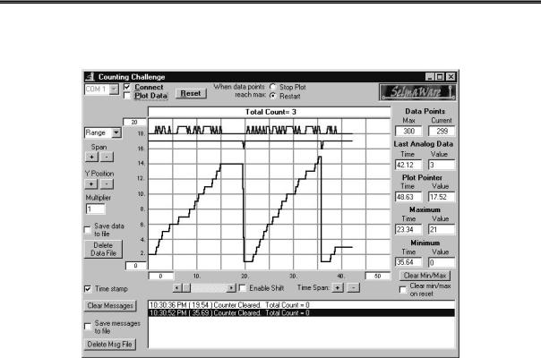
When PB1 is pressed, the program branches to the Count_it routine. Notice that the first line of this routine tests to see if the switch is open or Flag1 is set. Neither is true upon the first pass through the program. Therefore, Counts is incremented, Flag1 is set to 1 and program execution goes back to Loop. If PB1 still is being held down, Count_it is run again. This time, however, with Flag1 set, the IF-THEN statement sends the program back to Loop without incrementing Counts again. No matter how long the pushbutton is pressed, it will only register one “count” upon each closure. Although you are only incrementing the Count variable in this program, it could be part of a routine called for in an industrial application. Figure 2.9 is a screen shot that is representative of what you may see when running the program.
Industrial Control Version 1.1 •Page 41
Experiment #2: Digital Input Signal Conditioning
Figure 2.9: Running Program 2.4 - Edge Trigger Counting
Programming Challenge 1: The Parking Lot.
Use the indicating LEDs on output Pins 4 and 5, along with the two pushbuttons, to simulate a parking lot application. Assume your parking lot can hold 24 cars. Pushbutton PB1 will be counting cars as they enter the lot. Pushbutton PB2 will count cars as they leave. Write a program that will keep track of the total cars in the parking lot by counting “up” with PB1 and “down” with PB2. Have the green LED on as long as there is a vacancy in the lot. Turn the red LED on when the lot is full. Continually display how many parking spaces are available in the User Status window (!USRS). Plot continually the number of cars in the parking lot.
Additional StampPlot Lite Challenge
Keep a file of the number of times your parking lot went from “Vacancy“ to “Full” (see Appendix A and the StampPlot Lite help file for information on using the Save Data to File option).
Page 42 •Industrial Control Version 1.1

Experiment #2: Digital Input Signal Conditioning
BUTTON Command: PBASIC’s Debouncing Routine
Debouncing switches is a very common programming task. Parallax built into the PBASIC2 instruction set a command specifically designed to deal with digital input signal detection. The command is called button. The syntax for the command is shown below.
PBASIC Command Quick Reference: BUTTON
BUTTON pin, downstate,delay,rate,bytevariable,targetstate, address
•Pin: (0-15) The pin number of the input.
•Downstate: (0 or 1) Specifiying which logical state occurs when the switch is activated.
•Delay: (0-255) Establishes a settling period for the switch. Note: 0 and 255 are special cases. If delay is 0, Button performs no debounce or auto-repeat. If delay is 255, Button performs debounce but no auto-repeat.
•Rate: (0-255) Specifies the number of cycles between autorepeats.
•Bytevariable: The name of a byte variable needed as a workspace register for the BUTTON instruction.
•Targetstate: The state of the pin on which to have a branch occur.
•Address: The label to branch to when the conditions are met.
To try it with our counting routine, load and run program Program 2.5.
'Program 2.5: Button Exercise with StampPlot Interface
'Use Button to count and display the number of closures of PB1.
'Reset total count with a closure of PB2.
PAUSE 500 |
|
Counting Challenge",CR |
' Titles the StampPlot screen |
DEBUG "!TITL |
|||
DEBUG "!TMAX |
50",CR |
' Sets the plot time (seconds) |
|
DEBUG "!PNTS |
300",CR |
' Sets the number of data points |
|
DEBUG "!AMAX |
20",CR |
' Sets vertical axis (counts) |
|
DEBUG "!MAXR",CR |
' Reset after max data points is reached |
||
Wkspace1 |
VAR |
byte |
' Workspace for the BUTTON command for PB1 |
Wkspace1 |
= 0 |
byte |
' Must clear workspace before using BUTTON |
Wkspace2 |
VAR |
' Workspace for the BUTTON command for PB2 |
|
Wkspace2 |
= 0 |
|
' Must clear workspace before using BUTTON |
Counts VAR word |
' Word variable to hold count |
||
Counts = |
0 |
|
|
Loop: |
|
|
|
PAUSE 50 |
|
' Debounced edge trigger detection of PB1 |
|
BUTTON |
1,1,255,0,Wkspace1,1,Count_it |
||
BUTTON |
2,0,255,0,Wkspace2,1,Clear_it |
' Debounced edge trigger detection of PB2 |
|
Industrial Control Version 1.1 •Page 43

Experiment #2: Digital Input Signal Conditioning
DEBUG "!USRS Total Count = ", DEC Counts, CR
DEBUG DEC Counts, CR |
' Display total counts in Status box |
' Show counts on analog trace |
|
DEBUG IBIN In1, BIN In2, CR |
' Plot the digital status. |
GOTO Loop |
|
Count_it: |
' Increment Counts |
Counts = Counts +1 |
|
GOTO Loop |
|
Clear_it: |
' Clear counts to 0 |
Counts = 0 |
DEBUG "Counter Cleared. Total Count = ", DEC Counts, CR
' Display in Text Box
GOTO Loop
Review the documentation concerning the BUTTON command in the BASIC Stamp Programming Manual Version 1.9. This is a very handy command for industrial applications. Experiment by changing the delay time from 50 to 100 and to 200. See if you can press the switch more than one time but only get one Action to take place. What would be the risk of allowing for too much settling time in “high speed” counting applications? Save this program; it will be modified only slightly for use with the next programming challenge.
Electronic Digital Input Sources
It is very common for digital inputs to come from the outputs of other electronic circuits. These inputs may be from a variety of electronic sources, including inductive or capacitive proximity switches, optical switches, sensor signal-conditioning circuits, logic gates, and outputs from other microcontrollers, microprocessors, or programmable logic control systems.
There are several things to consider when interfacing these sources to the BASIC Stamp. Primarily: “Are they electrically compatible?”
1.Is the source’s output signal voltage within the BASIC Stamp input limits?
2.Is the ground reference of the circuit the same as that of the BASIC Stamp?
3.Is protection of either circuit from possible electrical failure of the other a concern such that isolation may be necessary?
Figure 2.10 shows a variety of electrical interfacing possibilities you may face.
Page 44 •Industrial Control Version 1.1

Experiment #2: Digital Input Signal Conditioning
Once a compatible signal is established, the next question becomes, “Is the program able to respond to the signal?”
1.Is digital bounce an issue?
2.How fast is the data? What is its frequency? What is the minimum pulse time?
3.Is action to be taken based on the data’s steady-state level or on its leading or trailing edges?
Techniques to deal with switch bounce and edge triggering that were discussed relative to the manual pushbuttons also apply to the electronic switch.
Industrial Control Version 1.1 •Page 45

Experiment #2: Digital Input Signal Conditioning
Figure 2.10: Input Interfacing of Electronics to the BASIC Stamp
(a)TTL and CMOS logic inputs powered from a +5-volt supply can be applied directly to the BASIC Stamp’s input pins. If the two systems are supplied from the same 5 volts, great. If not, at least the grounds must be common (connected together).
(b)Low-voltage (+3 V) devices can be interfaced using a 74HCT03 or similar open-drain gate with a pull-up resistor to the BASIC Stamp’s +5-volt supply. Supply the chip with the low-voltage supply and make the grounds common.
(c)Higher-voltage digital signals can be interfaced using a 74HC4050 buffer or 74HC4049 inverter powered at +5 volts. These devices can safely handle inputs up to 15 volts. Again, the grounds must be common.
(d)A referenced comparator op-amp configuration can establish a High/Low output based on the analog input being above or below the setpoint voltage. The LM358 is an op-amp whose output will go from ground to nearly Vdd on a single-ended, +5-volt supply. It will be used in the upcoming application.
(e)An opto-coupler may be used to interface different voltage levels to the BASIC Stamp. The LED’s resistor holds current to a safe level while allowing enough light to saturate the phototransistor. The input circuit can be totally isolated from the phototransistor’s BASIC Stamp power supply. This isolation provides effective protection of each circuit in case of an electrical failure of the other.
Page 46 •Industrial Control Version 1.1
Experiment #2: Digital Input Signal Conditioning
Exercise #4: An Electronic Switch
Electronic switches that provide “non-contact” detection are very popular in industrial applications. No physical contact for actuation means no moving parts and no electrical contacts to wear out. The pushbutton switch used earlier should be good for several thousand presses. However, its return spring eventually will fatigue, or its contacts will arc, oxidize, or wear to the point of being unreliable.
Industrial electronic switches operate on one of three principles.
•Inductive proximity switches sense a change in an oscillator’s performance when metal objects are brought near it. Most often the metal objects absorb energy via eddy currents from the oscillator causing it to stop.
•Capacitive proximity switches sense an increase in capacitance when any type of material is brought near them. When the increase becomes enough, it causes the switch’s internal oscillator to start oscillating. Circuitry is then triggered and the output state is switched.
•Optical switches detect the presence or absence of a narrow light beam, often in the infrared range. In retroreflective optical switches, the light beam may be reflected by a moving object into the switch’s optical sensor. Through-beam optical switches are set up such that the object blocks the light beam by going between the light source and the receiver.
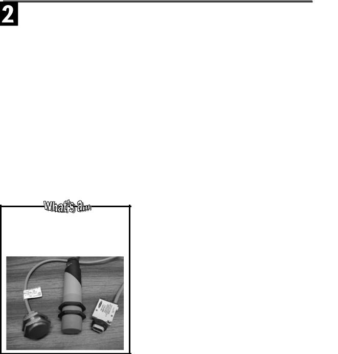
Proximity switch?
Proximity switches detect the presence of an object without contacting it. The switches below represent the three main categories:
Inductive, Capacitive, and Optical
The output of an electronic switch is a bi-state signal. It’s final stage may be any one of the types seen in Figure 2.10. As a technician and application developer, you must consider the nature of this signal circuit and condition it for the digital input of the microcontroller. The manufacturer’s datasheet will give you information on the operating voltage for the switch and typical load connections.
Although you can think of the BASIC Stamp’s digital input pin as the load, the electronic switch may require a reference resistor as used earlier in Figure 2.2. Most likely, the output of the proximity switch will be very near 0 volts in one state and near its supply voltage in the other state. It is always a good idea to test the switch’s output states with a voltmeter before applying it to the unprotected input of the microcontroller. If the output voltages are not within the compatible limits of the
Industrial Control Version 1.1 •Page 47

Experiment #2: Digital Input Signal Conditioning
BASIC Stamp, you will need to use one of the circuits in Figure 2.10 as an appropriate interface.
The following exercise focuses on the design and application of an optical switch. We will use this switch to detect and count objects. Then the switch will be used as a tachometer to determine RPM.
In Figure 2.11, the infrared light-emitting diode (LED) and the infrared phototransistor form a matched emitter/detector pair. Light emitted by the LED will result in phototransistor collector current. An increase in collector current drives the phototransistor toward saturation (ground). If the light is prevented from striking the phototransistor, it goes toward cutoff and the collector voltage increases positively. These conditions of light and no-light will most likely not provide a legal TTL signal at the collector of the transistor. Applying this signal to the input of a referenced comparator will allow us to establish a setpoint somewhere between the two conditions. The output of the comparator will be a compatible TTL logic signal. It’s level is dependant on which side of the setpoint the phototransistor’s output is on. The LM358 op-amp is a good choice for this application. It can operate on a +5-volt single supply and its output saturation voltages are almost equal to the supply potentials of +5 and ground.
Carefully construct the circuit in Figure 2.11 on the Board of Education breadboard. Mounting the devices near one end as pictured in the diagram allows for additional circuits in upcoming exercises. Make a 90o bend in the LED and phototransistor leads so the devices lie parallel to the the benchtop. The phototransistor and infrared LED should be placed next to each other, pointing off the edge of the breadboard.
The LED in Figure 2.11 is emitting a continuous beam of infrared light. With the LED and phototransistor side- by-side, there is little or no light coming into the phototransistor because there is nothing reflective in front of it. If an object is brought toward the pair, some of the LED light will bounce back into the phototransistor. When light strikes the phototransistor, the collector current will flow and the collector voltage will drop. In this setup, the scattered reflection of light off an object as it passes in front of the pair will be sensed by the phototransistor. The amount of reflected light into the sensor depends on the optical reflectivity of the target object and the geometry of the light beam. We will attempt to determine the presence of a flat-white object. With the emitter and detector mounted side-by-side, you will try for detection of the object at a distance of one inch.
You must make a couple of voltage measurements to calibrate the presence of the object. Begin by placing a voltmeter across the phototransistor’s collector and emitter. Measure the voltage when there is no object in front of the sensor. Record this value in Table 2.3. Next, move a white piece of paper toward and away from the pair and notice the variation in voltage. As the paper is brought near the IR pair, the reflected light increases collector current and drives the transistor toward saturation –“low.” Record the voltage reading with the white paper approximately one inch in front of the sensor in Table 2.3. The difference between these measurements may be quite small, like 0.5 V, but that will be enough to trigger the op-amp. This signal is applied to the inverting input of the LM358 comparator. The potentiometer provides the non-inverting input reference voltage. This reference should be a value between the “no reflection” and “full reflection” readings.
Page 48 •Industrial Control Version 1.1