

Industrial Control (Students guide, 1999, v1.1 )
.pdfExperiment #7: Real-time Control and Data Logging
Experiment #7: Real Time Control and Data Logging
Microcontrollers, such as the BASIC Stamp can be good at dealing with very short time periods, such as milliseconds or seconds, but there exist many processes that depend on keeping accurate track of real time (time of day) and possibly even the date or day of the week.
Some examples include heating controls for buildings to set the temperature lower after working hours to conserve power; annealing a metal by heating at different temperatures for specific time periods to temper or strengthen the metal; and logging data over long periods of time for later retrieval and analysis.
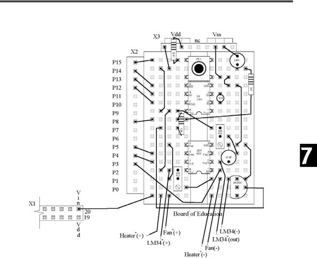
This experiment will explore taking action based on specific time of day, action taken based on time intervals, and logging and retrieving data. For this we will need to add real-time features to the circuit built in Experiment #5. Connect the DS-1302 Real Time Clock (RTC) as illustrated in Figure 7.1c and the pushbutton in Figure 7.1d. Figure 7.2 is a board layout sample for placing all the components.
The DS1302 RTC uses an external 32.767kHz crystal oscillator for a time base. Be sure to connect the crystal as close as possible to the IC to maximize time reliability (distance will create more error due to the capacitance effects of the breadboard). The RTC is similar to the BASIC Stamp in that data is stored in registers (RAM memory) that may be written and read. These registers hold the time and date as seconds, minutes, hours, month, etc. The DS1302 also has RAM available for general data storage by the user. For our purposes we will use only the time of day features of the chip. Please see the DS1302 data sheets and Parallax application notes concerning additional features.
Just as with the ADC0831 A/D converter, data is serially shifted into the BASIC Stamp 2 from the IC. This will allow us to access the current time as maintained by the DS1302. In order to set the current time, we can place the IC in a 'write-mode' and serially shift data from the BASIC Stamp 2 into the IC.
Data for the time (and date) is maintained in the DS1302 as Binary Coded Decimals (BCD). This is a subset of the Hexadecimal number base. In Hexadecimal (base 16) a byte is broken up into a high and low nibble, and each is read as a digit.
Industrial Control Version 1.1 •Page 189

Experiment #7: Real-time Control and Data Logging
Figure 7.1: Complete Circuit with Real Time Clock
Page 190 •Industrial Control Version 1.1
Experiment #7: Real-time Control and Data Logging
Figure 7.2: Sample Component Layout for Experiment #7
Take for example the binary number: 01000110. In binary, each place is a higher power of 2, and the decimal equivalent would be: 64+4+2 = 70. With an 8-bit binary number we have a possible decimal range of 0-255.
In Hexadecimal, the byte is broken down into nibbles and converted individually: 0100 0110
4 6
Industrial Control Version 1.1 •Page 191

Experiment #7: Real-time Control and Data Logging
This hexadecimal number is typically written as 86H (Intel format), $86 (Motorola format) or 8616 (Scientific format). Since a single unique number represents each nibble, we have a range in binary from 0000 to 1111, or decimal 0-15. In Hexadecimal the values of 10 to 15 are represented using the letters A to F. The hexadecimal full range of a byte of data is $00 to $FF. The binary number 10101110 is be represented in Hexadecimal as $AE.
Decimal |
Binary |
Hexadecimal |
Decimal |
Binary |
Hexadecimal |
0 |
0000 |
0 |
8 |
1000 |
8 |
1 |
0001 |
1 |
9 |
1001 |
9 |
2 |
0010 |
2 |
10 |
1010 |
A |
3 |
0011 |
3 |
11 |
1011 |
B |
4 |
0100 |
4 |
12 |
1100 |
C |
5 |
0101 |
5 |
13 |
1101 |
D |
6 |
0110 |
6 |
14 |
1110 |
E |
7 |
0111 |
7 |
15 |
1111 |
F |
In Binary Coded Decimal, each nibble is again used to represent a single digit, but since it is a coded DECIMAL number, the valid ranges can only be from 0-9 for each nibble. Our first example of 01000110 is 46BCD (a valid BCD number) and $46 (a valid hexadecimal number). Our second example of 10101110 would be $AE (valid hexadecimal), but an INVALID BCD value since A and E are not valid decimal numbers.
Our programs will use the hexadecimal notation in setting, or checking the times of the RTC. Additionally, the RTC is set to use a 24-hour clock, so a time of 1:00 PM will be 13:00.
Exercise #1: Real Time Control
In this first exercise we will simulate a night-setback thermostat of a building. During normal working hours, temperature will be kept at a higher temperature than during the night when energy conservation is needed. To simplify our code, we will use On/Off control instead of the more appropriate control of differential-gap.
Since we will be using our incubator, and to ensure the temperature is above your room temperature, we will use values 100F for working hours and 90 F for nighttime hours. The times for adjusting the temperature up for the day is at 6:00 AM, or 06:00 hours. The time to turn the thermostat down will be 6:00 PM or 18:00 hours.
Program 7.1 is the code for experiment.
Page 192 •Industrial Control Version 1.1

Experiment #7: Real-time Control and Data Logging
'Program 7.1 - Real Time On/Off-Control.
'This program will adjust temperture to 100F between the hours 'of 06:00 - 18:00 and 90F between 18:00 and 06:00.
'***** Initialize Settings ******* |
' Define initial time |
|||
Time |
= |
$0553 |
||
Seconds |
= |
$00 |
' Define time |
to go low temp. |
CTimeLow |
CON |
$1800 |
||
CTimeHigh |
CON |
$0600 |
' Define time |
to go high temp. |
LowTempSP |
CON |
900 |
' Define low temp in tenths of degrees. |
|
HighTempSP |
CON |
1000 |
' Define high |
temp in tenths of degrees. |
'********************************* |
|
|
||
GOSUB SetTime |
|
|
' Set RTC (Remark out if time ok) |
|
Setpoint = LowTempSP |
|
' Set initial |
temperature |
|
CTime = CTimeHigh |
|
' Set initial |
change time |
|
Seconds = $00 |
|
|
|
|
' Define A/D constants & variables |
|
|
||
CS |
CON |
3 |
' 0831 chip select active low from BS2 (P3) |
|
CLK |
CON |
4 |
' Clock pulse |
from BS2 (P4) to 0831 |
Dout |
CON |
5 |
' Serial data |
output from 0831 to BS2 (P5) |
Datain |
VAR |
BYTE |
' Variable to |
hold incoming number (0 to 255) |
Temp |
VAR |
WORD |
' Hold the converted value representing temp |
|
TempSpan |
CON |
5000 |
' Full Scale input span in tenths of degrees. |
|
Offset |
CON |
700 |
' Minimum temp. Offset, ADC = 0 |
|
Setpoint |
VAR |
WORD |
' Target Temperature |
|
'Define RTC Constants
'Register values in the RTC
SecReg |
CON |
%00000 |
|
MinReg |
CON |
%00001 |
|
HrsReg |
CON |
%00010 |
|
CtrlReg |
CON |
%00111 |
|
BrstReg |
CON |
%11111 |
|
'Constant for BS2 Pin connections to RTC |
|||
RTC_CLK |
CON |
12 |
' Clock pin |
RTC_IO |
CON |
13 |
' I/O pin |
RTCReset |
CON |
14 |
' Reset pin |
'Real Time variables |
BYTE |
|
|
RTCCmd |
VAR |
|
|
RTemp |
VAR |
BYTE |
|
Time |
VAR |
WORD |
' Word to hold full time |
Hours |
VAR |
TIME.HIGHBYTE |
' High byte is hours |
Industrial Control Version 1.1 •Page 193

Experiment #7: Real-time Control and Data Logging
Minutes |
VAR |
TIME.LOWBYTE |
' |
Low byte is hours |
Seconds |
VAR |
BYTE |
|
|
'Time to change variables |
' |
Word to hold full time |
||
CTime |
VAR |
WORD |
||
CHours |
VAR |
CTime.HIGHBYTE |
' |
High byte is hours |
CMinutes |
VAR |
CTime.LOWBYTE |
' |
Low byte is minutes |
CSeconds |
VAR |
Byte |
|
|
'Configure Plot |
|
|
' |
Allow buffer to clear |
PAUSE 500 |
|
|
||
DEBUG "!RSET",CR |
|
' |
Reset plot to clear data |
|
DEBUG "!TITL Timer On/Off Control",CR |
' |
4000 sample data points |
||
DEBUG "!PNTS 4000",CR |
|
|||
DEBUG "!TMAX 900",CR |
|
' |
Max 900 seconds |
|
DEBUG "!SPAN 70,120",CR |
' |
70-120 Degrees |
||
DEBUG "!AMUL 0.1",cr |
|
' |
Multiply data by 0.1 |
|
DEBUG "!CLMM",CR |
|
' |
Clear Min/Max |
|
DEBUG "!CLRM",CR |
|
' |
Clear messages |
|
DEBUG "!TSMP ON",CR |
|
' |
Time Stamp on |
|
DEBUG "!SHFT ON",CR |
|
' |
Enable plot shift |
|
DEBUG "!PLOT ON",CR |
|
' |
Start plotting |
|
DEBUG "!RSET",CR |
|
' |
Reset plot to time 0 |
|
Main: |
|
|
|
|
PAUSE 500 |
|
|
|
|
GOSUB ReadRTCBurst |
|
|
||
GOSUB TimeControl |
|
|
||
GOSUB Getdata |
|
|
|
|
GOSUB Calc_Temp |
|
|
|
|
GOSUB Control |
|
|
|
|
GOSUB Display |
|
|
|
|
GOTO Main |
|
|
|
|
Getdata: |
|
|
' |
Acquire conversion from 0831 |
LOW CS |
|
|
' |
Select the chip |
LOW CLK |
|
|
' |
Ready the clock line. |
SHIFTIN Dout, CLK, MSBPOST,[Datain\9] ' |
Shift in data |
|||
HIGH CS |
|
|
' |
Stop conversion |
RETURN |
|
|
|
|
Calc_Temp: |
|
|
' |
Convert digital value to |
Temp = TempSpan/255 * Datain/10 + Offset' temp based on Span & Offset variables. |
||||
RETURN |
|
|
|
|
Control: |
|
|
' |
Maintain temperature around setpoint |
IF Temp > SetPoint THEN OFF |
|
|
||
HIGH 8
RETURN
Off:
LOW 8
RETURN
Page 194 •Industrial Control Version 1.1

Experiment #7: Real-time Control and Data Logging
Display: 'Display real time and time for next change and send data for plotting DEBUG "!USRS Current Time:", HEX2 hours,":",HEX2 Minutes,":",HEX2 seconds DEBUG " Next Change at:",HEX2 Chours,":",HEX2 CMinutes,CR
DEBUG DEC Temp,CR
DEBUG IBIN OUT8,CR RETURN
SetTime:
'****** Initialize the real time clock to start time RTemp = $10 : RTCCmd = CtrlReg : GOSUB WriteRTC
'Clear Write Protect bit in control register
RTemp = Hours : |
RTCCmd |
= |
HrsReg : |
GOSUB WriteRTC ' Set initial hours |
||||
RTemp = Minutes |
: RTCCmd |
= |
MinReg |
: GOSUB |
WriteRTC ' Set initial minutes |
|||
RTemp |
= |
Seconds |
: RTCCmd |
= |
SecReg |
: GOSUB |
WriteRTC ' Set initial seconds |
|
RTemp |
= |
$80 : RTCCmd = |
CtrlReg : GOSUB WriteRTC |
|||||
'Set write-protect bit in control register
Return |
|
WriteRTC: |
'Write to DS1202 RTC |
HIGH RTCReset |
|
SHIFTOUT RTC_IO, RTC_CLK, LSBFIRST, [%0\1,RTCCmd\5,%10\2,RTemp] |
|
LOW RTCReset |
|
RETURN |
|
ReadRTCBurst: |
'Read all data from RTC |
HIGH RTCReset |
|
SHIFTOUT RTC_IO, RTC_CLK, LSBFIRST, [%1\1,BrstReg\5,%10\2] |
|
SHIFTIN RTC_IO, RTC_CLK, LSBPRE, [Seconds,Minutes,Hours] |
|
LOW RTCReset |
|
RETURN |
|
TimeControl: |
'See if time for a change |
IF (Time = CTimeLow) AND (Setpoint = HighTempSP) THEN LowTemp |
|
IF (Time = CTimeHigh) AND (Setpoint = LowTempSP) THEN HighTemp |
|
Return |
|
LowTemp: |
'Change to evening temperatures |
Setpoint = LowTempSP |
|
DEBUG "Time: ", HEX2 |
Hours,":",HEX2 Minutes,":",HEX2 Seconds |
DEBUG "-- Setpoint = |
", DEC SetPoint/10,".0",CR |
CTime = CTimeHigh |
|
RETURN |
|
HighTemp: |
'Change to daytime temperatures |
Setpoint = HighTempSP |
hours,":",HEX2 minutes,":",HEX2 seconds |
DEBUG "Time: ", HEX2 |
|
DEBUG "-- Setpoint = |
",DEC SetPoint/10,".0",CR |
CTime = CTimeLow |
|
RETURN |
|
Industrial Control Version 1.1 •Page 195
Experiment #7: Real-time Control and Data Logging
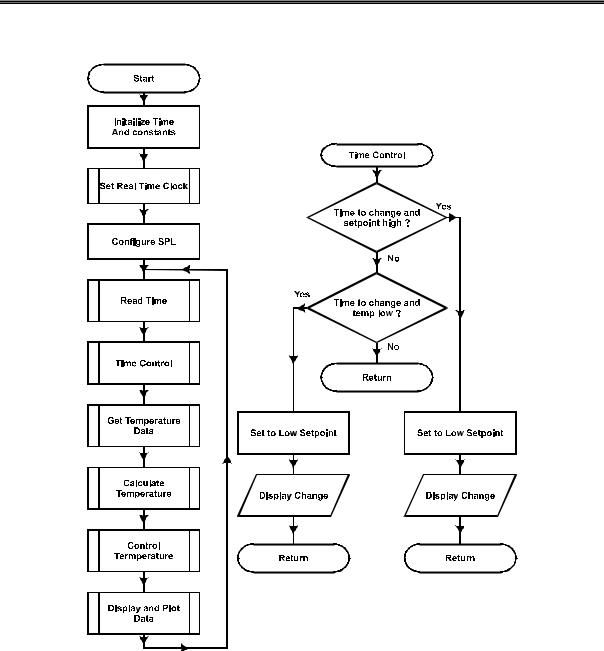
Figure 7.3: Night Setback Flowchart
Page 196 •Industrial Control Version 1.1

Experiment #7: Real-time Control and Data Logging
Note that the program will reset the time to 05:53 every time the BASIC Stamp is reset. This can occur from program loading, manual Stamp reset, power supply cycling, and sometimes the COM port or computer cycling. The start time is appropriate for what we are discussing in this section, but in later sections you may want to set the values of the start-time to actual values.
'***** Initialize Settings ******* |
' Define initial time |
||
Time |
= |
$0553 |
|
Seconds |
= |
$00 |
' Define time to go low temp. |
CTimeLow |
CON |
$1800 |
|
CTimeHigh |
CON |
$0600 |
' Define time to go high temp. |
LowTempSP |
CON |
900 |
' Define low temp. |
HighTempSP |
CON |
1000 |
' Define high temp. |
'********************************* |
' Set RTC (Remark out if time ok) |
||
GOSUB SetTime |
|
|
|
Note: If power is removed from the DS1302 Real Time Clock it will power-up with unpredictable values in the time registers with Gosub SetTime remarked out.
The times for changing temperature and their new values are also set here. GOSUB SetTime sets the real time clock to the specified time. Once the proper time is set, this line may be remarked out and downloaded again to prevent the time from being reset to 05:53 if the BASIC Stamp is reset.
The program uses two sets of variables for time, one to set/hold the current time, and another to hold the time we wish to change the thermostat. Note that the word variable of Time and CTime are further broken down into Hours and Minutes:
Time |
VAR |
WORD |
' Word to hold |
full |
time |
|
Hours |
VAR |
TIME.HIGHBYTE |
' |
High byte is |
hours |
|
Minutes |
VAR |
TIME.LOWBYTE |
' |
Low byte is hours |
|
|
The variable Hours is assigned to be the high byte of the word variable Time, or those two BCD positions representing the hour. The same is true for minutes and the lower 2 positions. This is a very powerful tool when parts of a single variable need to be addressed individually.
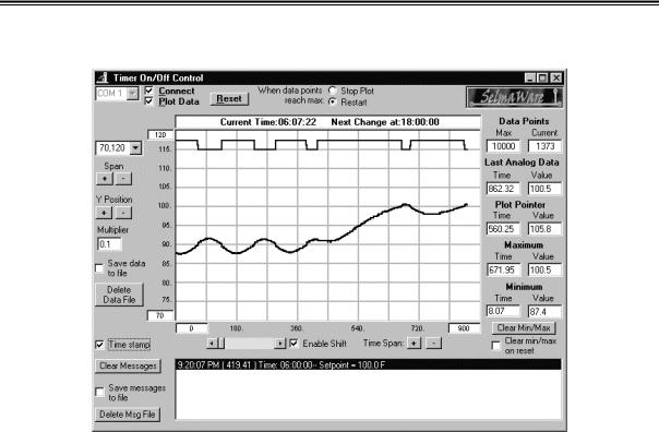
Program 7.1 starts time 7 minutes before switching to the working-hours temperature. This should provide time for temperature to stabilize at the lower temperature. Figure 7.4 is a plot of the run.
Industrial Control Version 1.1 •Page 197
Experiment #7: Real-time Control and Data Logging
Figure 7.4: Time-Controlled 'Building Heating’
The StampPlot Lite user status box displays the current time and the time that the next change is set to occur. The time in the status box may appear to be changing at irregular intervals, but that is a result of timing of the BS2 in displaying the data and not the time kept by the RTC. The message area displays both the time a change occurred and the new setpoint.
The plot illustrates On/Off control at the 90 F setpoint, and the switch to the 100 F setpoint at 06:00. Using the RTC, adding more output devices, and expanding the control section of the code, we could add numerous time-based events to occur over the course of a day.
Download and run program 7.1. Monitor with StampPlot Lite through at least the 06:00 change. You will need to wait another 12 hours to see if it switches back to the low setpoint at 18:00... Have time to wait?
Page 198 •Industrial Control Version 1.1