

Industrial Control (Students guide, 1999, v1.1 )
.pdfExperiment #5: Closed-Loop Control
Figure 5.2: Closed-Loop Control Circuitry
Industrial Control Version 1.1 •Page 129

Experiment #5: Closed-Loop Control
If the circuit isn’t already on your board, carefully construct it. Use space on the small Board of Education efficiently to allow for the circuitry. Take your time, plan your layout, and be careful not to inadvertently short any wires. Refer back to Experiment #4 for details on the film canister construction, the operation of the LM34, and the use of the ADC0831 analog-to-digital converter.
Double-check the Zero and Span voltages of the ADC0831. Use your voltmeter to set the Zero voltage (Vin(-))
to .7 and the Span (V(ref)) to .5 volts. This will establish a full-scale temperature measurement range from 70 to 120 degrees F.
Exercises
Exercise #1: Establishing Closed-Loop Control
Let’s assume it is our objective to maintain temperature within the canister at 101.50 oF + 1 degree. This would be representative of the requirements of an incubator used for hatching eggs. Maintaining the eggs at the setpoint temperature of 101.5 oF is perfect, but the temperature could go up to 102.50 or down to 100.50 without damage to the embryos. Although it may be hard to imagine an incubator when you look at your film canister, the BASIC Stamp would be well suited as the controller in a large commercial hatchery incubator.
To maintain temperature at the desired value seems like a pretty “common sense” task. That is, simply measure temperature; if it is above the setpoint, turn the heater OFF; and, if it is below, turn the heater ON. The simplest kind of control mode is on-off control. There are drawbacks to this control mode, however. During the following exercise, you will establish on-off control of your model incubator. Pay close attention to the characteristics exhibited by your model. These characteristics would also apply to real control applications.
Procedure
Programming for this application requires data acquisition, evaluation, and control action. Our display routine will also include storing and displaying the minimum and maximum overshoot in the process.
The structure and much of the content of Program 4.1 may be used to acquire and calculate our measurement. Instead of turning the heater on continually, a new subroutine will be added to evaluate and control it. Evaluation will be based on a setpoint variable. Refer to Program 5.1 following.
Page 130 •Industrial Control Version 1.1

Experiment #5: Closed-Loop Control
'Program 5.1: Simple ON/OFF Control with the StampPlot Interface
'This program establishes simple ON/OFF control of the model incubator. 'Program I/O is based on the circuitry of Figure 5.2.
'Zero and Span voltages: Digital 0 = Vin(-) =.70V and Span = Vref = .50V.
'Configure Plot Pause 500
DEBUG "!RSET",CR
DEBUG "!TITL Simple ON/OFF Control",CR DEBUG "!PNTS 60000",CR
DEBUG "!TMAX 300",CR DEBUG "!SPAN 70,120",CR DEBUG "!AMUL .1",CR DEBUG "!DELD",CR
DEBUG "!CLMM",CR
DEBUG "!CLRM",CR DEBUG "!USRS ",CR DEBUG "!SAVD ON",CR DEBUG "!TSMP ON",CR DEBUG "!SHFT ON",CR DEBUG "!PLOT ON",CR DEBUG "!RSET",CR
' Define constants & variables
CS CON 3
CLK CON 4
Dout CON 5
Datain VAR byte
Temp VAR word
TempSpan VAR word
TempSpan = 5000
Offset VAR word
Offset = 700
Setpoint VAR word
Setpoint = 1015
MMFlag VAR bit
MMFlag = 0
LOW 8
Main:
'Allow buffer to clear 'Reset plot to clear data 'Caption form
'60000 sample data points 'Max 300 seconds
'70-120 degrees 'Multiply data by .1 'Delete Data File 'Clear Min/Max 'Clear Messages
'Clear User status bar 'Save Data
'Time Stamp On 'Enable plot shift 'Start Plotting 'Reset plot to time 0
'0831 chip select active low from BS2 (P3)
'Clock pulse from BS2 (P4) to 0831
'Serial data output from 0831 to BS2 (P5)
'Variable to hold incoming number (0 to 255)
'Hold the converted value representing temp
'Full Scale input span in tenths of degrees
'Declare span 50 (1/100ths degrees)
'Minimum temp. Offset, ADC = 0
'Declare zero Temp. Set Vin(-) to .7 and 'Offset will be 700 tenths degrees. At these 'settings, ADC output will be 0 - 255 for 'temps
'of 700 to 1200 tenths of degrees.
'Initialize setpoint to 101.5 degrees
'Initialize heater OFF
Industrial Control Version 1.1 •Page 131

Experiment #5: Closed-Loop Control
GOSUB Getdata
GOSUB Calc_Temp
GOSUB Control
GOSUB Display
GOTO Main
Getdata: LOW CS LOW CLK
PULSOUT CLK,10
SHIFTIN Dout, CLK, MSBPOST,[Datain\8] HIGH CS
RETURN
Calc_Temp:
Temp = TempSpan/255 * Datain/10 + Offset
RETURN
Control:
IF Temp > Setpoint THEN OFF
HIGH 8
RETURN
OFF:
LOW 8
RETURN
'Acquire conversion from 0831 'Select the chip
'Ready the clock line.
'Send a 10 uS clock pulse to the 0831 'Shift in data
'Stop conversion
'Convert digital value to 'temp based on Span & 'Offset variables.
'ON/OFF control
'Heater ON
'Heater OFF
Display: |
'Plot Temp and heater status |
IF OUT8 = 0 AND MMFlag = 0 THEN MMClear ' Clear Min/Max |
|
DEBUG DEC Temp,CR |
|
DEBUG IBIN OUT8,CR |
|
RETURN |
|
MMClear: |
'Clear Min/Max When setpoint is first reached. |
DEBUG "!CLMM",CR |
|
DEBUG "!USRS Overshoot/Undershoot Test Ready",CR
MMFlag = 1
RETURN
Page 132 •Industrial Control Version 1.1

Experiment #5: Closed-Loop Control
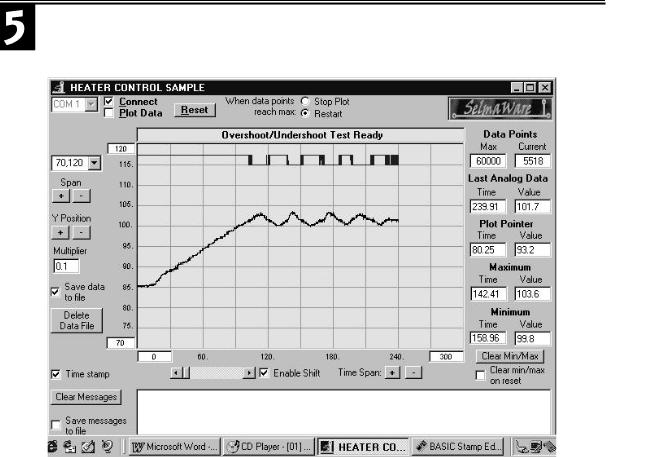
Run the program and observe the behavior of the system. StampPlot Lite will graphically plot the temperature response of the system and the on-off status of Output 8. Follow the StampPlot Lite procedures of running the program, closing the debug window, opening StampPlot Lite, and pressing the “reset” button.
When you start your system, the heater will be on as indicated by the LED. The heater/resistor becomes quite hot when full power is applied. This heat transfers through the environment and warms the temperature sensor. When the sensor has heated to 101.5, the BASIC Stamp will turn off the heater. For a period after the heater is turned off, the temperature continues to rise. This is called overshoot. At this point, it is important to understand the dynamics of your system. The heat held within the mass of the resistor will continue to dissipate into the air, the air becomes warmer, and the LM34 reports that overshoot has occurred. Similar to the mechanical inertia of a moving object, this phenomenon is called thermal inertia. Overshoot becomes large when the heat energy contained in the mass of the resistor is large, relative to the heat already in the canister. The 35-mm canister is small, but the mass of the half-watt resistor also is small. As a result, the overshoot of your system will probably be less than one degree.
When the temperature does turn around and begin to fall, as it passes the setpoint, the heater is once again turned on. Undershoot will occur for similar reasons as did the overshoot. During the time the heater is coming up in temperature, the ambient temperature has continued downward. Continuous cycling above and below the desired setpoint is typical of on-off control. The rate of this cycling and the degree of the overshoot depend on the characteristics of the system. On-off control is suitable for processes that have large capacity, can tolerate sluggish response, and sustain a relatively constant level of disturbance. If our incubator were large, well insulated, and kept in a constant room environment, on-off control would be acceptable. After the process has had a chance to cycle a few times, record the minimum and maximum overshoot values.
Maximum overshoot _______________ Minimum Overshoot __________________
Using your cursor, investigate time between cycles. Record these times below.
Time at which the heater first turned OFF (T1off): |
____________ |
Time at which the heater turned back ON (T1on): |
____________ |
Time at which the heater turned OFF again (T2off): |
____________ |
Cycle time = (T2off) – (T1off): |
____________ |
Industrial Control Version 1.1 •Page 133

Experiment #5: Closed-Loop Control
A major problem with on-off control is that the output drive may cycle rapidly as the measurement hovers about the setpoint. Noise riding on the analog sensor measurement would be interpreted as rapid fluctuation above and below the setpoint. The timing diagram in Figure 5.3 represents this problem
Figure 5.3: On-Off Control When Noise Rides on the Data
Heat ON
Setpoint
Heat OFF
The slow-moving data that is cycling through the setpoint has a high-frequency noise component riding on it. As you can see, the coupled effects of the noise results in the data passing above and below the setpoint several times. The microcontroller would attempt to turn the heating element on and off accordingly.
In an actual incubator application where larger amounts of power are controlled, this rapid switching could cause unwanted RF noise. This rapid cycling could also be damaging to electromechanical output elements such as motors, relays, and solenoids.
Do you observe the rapid cycling of the LED as the temperature approaches the setpoint? ___________
Remove the 10-uF capacitor from across the sensor output. Does this increase the cycling problem? Why? Figure 5.4 is a typical screen shot resulting from this experiment. Overshoot and rapid cycling are a problem. Is this similar to your system’s response?
Page 134 •Industrial Control Version 1.1
Experiment #5: Closed-Loop Control
Figure 5.4: Simple ON/OFF Control
Industrial Control Version 1.1 •Page 135

Experiment #5: Closed-Loop Control
Challenge! Change the Dynamics of Your System
1.Connect your brushless fan to the Vcc supply and aim it toward the canister. Reset the program and watch the control action. Describe any effect that the new level of disturbance has on the overshoot and/or the cycling. Summarize how you have changed the dynamics of your system.
2.Place a single glass marble in your canister. Reset the program and watch the control action. Describe any effect that changing the mass of your system has on the overshoot and/or the cycling. Summarize how you have changed the dynamics of your system.
Exercise #2: Differential-Gap Control
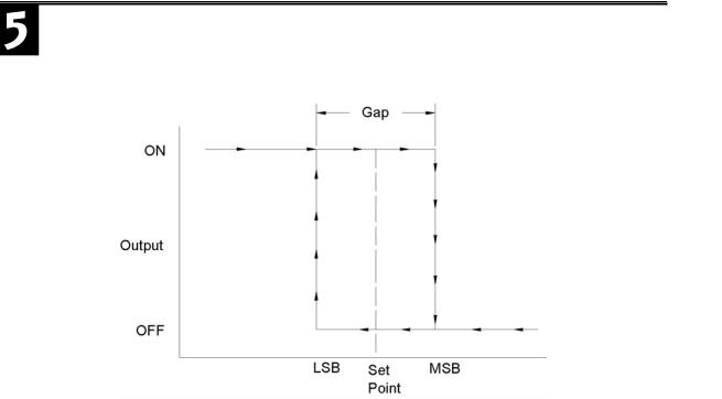
The rapid cycling resulting from noise or the measurement hovering around a single setpoint is the biggest disadvantage of simple on-off control. Most practical on-off control systems lend themselves to allowing a minimum and maximum value of measurement. An incubator is a good example. Although the desired temperature is 101.5 degrees, it allows + 1 degree of variance about the setpoint. Differential-gap control is a mode of control that takes action based on the measurement crossing a defined upper and lower limit. When the measured value goes beyond one limit, full appropriate action is taken to drive the temperature to the opposite limit. Full opposite action is then taken to drive the process back again. Figure 5.5 graphically diagrams the action taken by differential-gap control. When the system is started and its temperature is below the Lower limit, the heater will come on and the temperature rise. When the temperature passes the upper limit, the heater is turned OFF, heat will begin to leave the process, and the temperature will begin to drop to below the Lower limit. The heat then is turned back on and the cycle begins again.
Page 136 •Industrial Control Version 1.1
Experiment #5: Closed-Loop Control
Figure 5.5: Differential-Gap Control Action
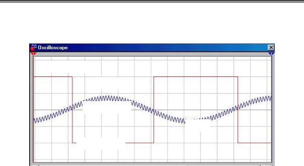
The result is a slower on-off cycle time and no cycling resulting from noisy data. Notice how the timing diagram in Figure 5.6 differs from the earlier one depicting noisy data in a simple on-off control mode.
Whenever the measurement is anywhere between these limits, the heater state is not changed. The result is a slower ON/OFF cycle time and no cycling from noisy data. The heater is switched when the data (+noise) passes a limit. After that, the data (+noise) has to exceed the other limit before switching will occur again. Because the differential gap is wider than the effect of the noise, rapid cycling is eliminated.
Industrial Control Version 1.1 •Page 137
Experiment #5: Closed-Loop Control
Figure 5.6: Differential-Gap Control Action when Noise is Riding on the Data
Heat ON
UTP
Desired Value
LTP
Heat OFF
These advantages come at the compromise of allowing the measured variable to drift further from the desired “average” value. The thermal inertia of our system will still result in some amount of overshoot and undershoot. We are accepting a wider variance in temperature. When processes allow this variance, differential-gap control is usually preferred over simple on-off control.
The Control subroutine can be easily changed to accommodate differential-gap control. Make the following modifications to Program 5.1.
Declare the new variables of Upper_limit and Lower_limit at the beginning of the program and initialize them to 102 oF and 101 oF respectively.
Upper_limit VAR |
word |
|
||
Lower_limit VAR |
word |
‘102 degrees in 1/10ths |
||
Upper_limit |
= |
1020 |
||
Lower_limit |
= |
1010 |
'101 degrees in 1/10ths |
|
Page 138 •Industrial Control Version 1.1