

Industrial Control (Students guide, 1999, v1.1 )
.pdfExperiment #4: Continuous Process Control
You will put the 47-ohm resistor and the temperature sensor inside the 35-mm film canister. Leads from these devices will come back to the Board of Education. Placing the cap on the canister creates a closed environment. High current through the resistor will heat the environment, and the sensor will convert temperature to an analog voltage. A current-boost transistor from Experiment #3 will drive the resistor/heater, and you will add an analog-to-digital converter to get binary temperature information into the BASIC Stamp. Figure 4.1 depicts this construction step. Follow the procedures on the next page to construct the canister environment and signal-conditioning circuitry.
Figure 4.1: Film Canister Heated Environment
Industrial Control Version 1.1 •Page 99

Experiment #4: Continuous Process Control
Preliminary Preparation
The 35-mm film canister has two holes drilled in it. The sensor and the “heater” will be placed into these holes.
In the last exercise, we controlled the on-off status of a 47-ohm resistor acting as a heating element. The current-boost transistor acts as a switch, controlling the unregulated 9-volt supply to the resistor. As you should have seen, when the transistor turned on, the 9-volt supply was placed across the resistor and it became quite warm, since the power consumed was P = V2/R= 92/47, or 1.7 watts! This is beyond the resistor’s half-watt rating, but we are using it as a heater. It may become discolored, but should be all right otherwise.
Place the resistor through the lower hole in the canister. Bend the leads and tape them down to the outside of the canister so the resistor is suspended in the middle of the canister.
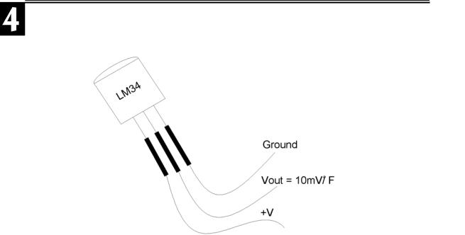
The LM34 probe will be used to measure the temperature of our system. The LM34 is an excellent sensor in terms of its linearity, cost, and simplicity. The sensor’s output voltage changes 10 mV per degree Fahrenheit and is referenced at 0 degrees. With a DC power supply and a voltmeter, you have a ready-made Fahrenheit temperature sensor.
Refer to Figure 4.2 and the device’s datasheet in Appendix D.
Page 100 •Industrial Control Version 1.1
Experiment #4: Continuous Process Control
Figure 4.2: LM34 Temperature Probe
Test your temperature probe by connecting your probe to the +5-volt Vdd supply and ground. Use your voltmeter to monitor the LM34 output voltage of .01 volts per degree F. Simply move the decimal of the meter reading two places to the right to convert to temperature. For example; .75 V = 75 oF; .825 V = 82.5 oF;
1.05V = 105 oF, etc. Then, try this:
•Measure and record the room temperature.
•Hold the device between your fingers and watch the temperature rise.
•Hold it until the temperature becomes stable. How hot are your fingertips?
•The LM34 can measure temperatures up to 300 degrees. Briefly wave a flame under it and monitor higher temperatures.
Now, insert the sensor through the top hole of the film canister. Bend and tape its leads to the canister so the sensor is suspended inside. Cap your canister, and your model environment is complete. Keep in mind that although our laboratory setup is small and low power, it could represent controlling the temperature of a large kiln, a brewing vat, or an HVAC system. Appropriate output signal conditioning identified in Experiment #3 can allow the BASIC Stamp to control almost any industrial device.
Industrial Control Version 1.1 •Page 101

Experiment #4: Continuous Process Control
Next, let’s turn our attention to the Board of Education and set up the circuitry necessary for the experiment. Figure 4.3 represents the four circuits used in the exercises. All four circuits can fit on the Board of Education; you just have to be efficient with your use of the space. Figure 4.3a is a simple active-high pushbutton switch. It will be used to toggle the heater on and off. The output drive circuit depicted in Figure 4.3b also is very simple. Your board will contain the current-boost transistor (from Experiment 3) to drive the heater. Notice that an LED and current-limiting resistor have been added to indicate the status of this drive circuit. Note also that this circuit goes to the +5 Vdd supply, not the 9-volt unregulated supply.
Since the BASIC Stamp microcontroller does not have analog input capability, we must add an analog-to- digital converter to change the analog output of the LM34 temperature sensor to digital data. A one-step solution to signal conditioning is to use the serial analog-to-digital converter shown in Figure 4.3c. National’s ADC0831 is a suitable A/D converter for our application, and will prove to be a very useful device for this and future applications. It’s worth a moment at this point to look at the device’s features and limitations.
This converter will take an input voltage and convert it to 8-bit digital data with a range of 256 possible binary representations. Potentiometers can be used to externally set the analog voltage range spanned by the 0 to 25510 digital output capability of the ADC0831. The voltage at Vin(-) Pin 3 sets the zero value. The Vref voltage at Pin 5 sets the voltage span above Vin(-) over which the resolution of 255 is spread. Setting Vin(-) to .7 will reference the span of coverage at 70 degrees. Vref set to .5 volts results in a span of coverage of 50 degrees.
Page 102 •Industrial Control Version 1.1

Experiment #4: Continuous Process Control
Figure 4.3: Process Control Circuitry
Industrial Control Version 1.1 •Page 103

Experiment #4: Continuous Process Control
These voltages are used to focus the range of the A/D device to cover the analog voltage being converted. The application will operate from room temperature (70o) up to 120 oF. This temperature range equates to an LM34 voltage output of .70V to 1.20V. To maximize resolution, the span of interest is .5 V (1.2V-.7v); and the zero reference, termed the offset, is .7 V. Since we focus on just this range, each binary step represents approximately 0.2 degrees. This allows us to accurately resolve the temperature.
Construct the A/D converter circuit on the Board of Education. By using multi-turn trim potentiometers, the reference and span voltage levels can be set very accurately. Carefully measure and adjust these potentials. Attach the output of the LM34 to the input of the A/D converter.
Controlling the ADC0831 is relatively simple. A program control line tells the device to make a conversion. Once a conversion has been performed, the binary value can be output one bit at a time to the BASIC Stamp. The serial flow of data from the converter is controlled by output pins of the BASIC Stamp driving the “chip select” and “clock” lines. The chip select line (CS) is set low, followed by a low-to-high clock pulse. This starts the conversion. Subsequent clock pulses initiate the transfer of each binary bit starting with the most significant bit first. Parallax provides a convenient instruction, called SHIFTIN, specifically designed for controlling synchronous serial communication. Once the binary data is clocked into the BASIC Stamp, it is converted to temperature, based on the zero and spanning values. (The use of the ADC0831 is detailed in the Parallax Basic Analog and Digital text, which can be used as a further reference to this section.)
Program 4.1 has been written to test your converter and driver circuits, and exercise the StampPlot Lite Interface. The first section of the program configures StampPlot Lite. A section that establishes variables and constants follows this. The program is designed for the circuit of Figure 4.3. Double-check the proper connections to I/O Pins 1,3,4,5 and 8. Accurately set the Zero and Span voltages of the ADC0831 to .7 and .5, respectively.
Load the program. Running the program will result in the DEBUG window opening and scrolling values and messages to the screen. Close the DEBUG window and open the StampPlot Lite Interface. At this point, select the appropriate COM port and check “Connect.” Momentarily press the “Reset” button on the BASIC Stamp Board of Education to load the configuration and begin plotting the data. The user-status box will report the current temperature and the output of the A/D converter’s binary and decimal values. The temperature and status of the heater will be plotted on the interface. Pressing PB1 will TOGGLE the heater ON and OFF. (Feel free to omit the comments from this code, if you wish).
Page 104 •Industrial Control Version 1.1

Experiment #4: Continuous Process Control
'Program 4.1: Analog-to-Digital & ON-OFF test with StampPlot Interface
'Pushbutton P1 toggles the heater fully ON and OFF. It then establishes
'constants and variables used to acquire data from the ADC0831 serial A-to-D. 'StampPlot is used to graphically display results. Program assumes that the 'circuitry is set according to Figure 4.3. ADC0831: "chip select" CS = P3, "clock" 'Clk=P4, & serial 'data output"Dout=P5. ‘Zero and Span pins: Digital 0 = Vin(-) = '.70V and Span = Vref = .50V.
'Configure Plot |
' Allow buffer to clear |
|
Pause 500 |
||
DEBUG "!RSET",CR |
' Reset plot to clear data |
|
DEBUG "!TITL HEATER CONTROL SAMPLE",CR |
'Caption form |
|
DEBUG "!PNTS 6000",CR |
' 6000 sample data points |
|
DEBUG "!TMAX 600",CR |
' Max 600 seconds |
|
DEBUG "!SPAN 70,120",CR |
' 70-120 degrees |
|
DEBUG "!AMUL .1",CR |
' Multiply data by .1 |
|
DEBUG "!DELD",CR |
' Delete Data File |
|
DEBUG "!SAVD ON",CR |
' Save Data |
|
DEBUG "!TSMP ON",CR |
' Time Stamp On |
|
DEBUG "!CLMM",CR |
' Clear Min/Max |
|
DEBUG "!CLRM",CR |
' Clear Messages |
|
Debug "PLOT ON”,CR |
' Start Plotting |
|
DEBUG "!RSET",CR |
' Reset plot to time 0 |
|
' Define constants & variables
CS CON 3
CLK CON 4
Dout CON 5
Datain VAR byte
Temp VAR word
TempSpan VAR word
TempSpan = 5000
Offset VAR word
Offset = 700
'0831 chip select active low from BS2 (P3)
'Clock pulse from BS2 (P4) to 0831
'Serial data output from 0831 to BS2 (P5)
'Variable to hold incoming number (0 to 255)
'Hold the converted value representing temp
'Full Scale input span in tenths of degrees.
'Declare span. Set Vref to .50V and
'0 to 255 res. will be spread over 50
'(hundredths).
'Minimum temp. @Offset, ADC = 0
'Declare zero Temp. Set Vin(-) to .7 and
'Offset will be 700 tenths degrees. At these
'settings, ADC output will be 0-255 for temps
'of 700 to 1200 tenths of degrees.
Wkspace1 VAR byte |
' Workspace |
for the |
PB1's BUTTON command |
|
Wkspace1 = 0 |
' |
Clear the |
workspace before using BUTTON |
|
LOW 8 |
' |
Initialize heater |
OFF |
|
Main:
Industrial Control Version 1.1 •Page 105

Experiment #4: Continuous Process Control
GOSUB Getdata
GOSUB Calc_Temp
GOSUB Control
GOSUB Display
GOTO Main
Getdata: |
' Acquire conversion from 0831 |
|
LOW CS |
' Select the chip |
|
LOW CLK |
' Ready the clock line. |
|
PULSOUT CLK,10 |
' Send a 10 uS clock pulse to the 0831 |
|
SHIFTIN Dout, CLK, MSBPOST,[Datain\8] |
' Shift in data |
|
HIGH CS |
' Stop conversion |
|
RETURN |
|
|
Calc_Temp: |
' Convert digital value to |
|
Temp = TempSpan/255 * Datain/10 + Offset |
' temp based on Span & |
|
RETURN |
' Offset variables. |
|
Control: |
' Manual heater control |
|
BUTTON 1,1,255,0,Wkspace1,1,Toggle_it |
|
|
RETURN |
|
|
Toggle_it: |
|
|
TOGGLE 8 |
|
|
RETURN |
|
|
Display: |
' Plot Temp, binary ADC, & Temp status |
|
DEBUG DEC Temp,CR |
|
|
DEBUG IBIN OUT8,CR |
ADC Data in = %", BIN Datain, " |
Decimal", |
DEBUG "!USRS Temperature = ", DEC Temp," |
||
DEC Datain, CR |
|
|
RETURN |
|
|
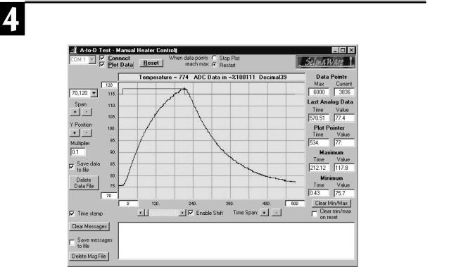
The StampPlot Lite interface will give you a dynamic representation of temperature changes in your canister. Toggle the heater ON and OFF and watch the response. The screen shot in Figure 4.4 represents the closed canister heating to 120 degrees and then cooling after the heater is turned off. Play with your system to become more familiar with its response; then, let’s take a little closer look at the subroutines that make up the program.
Page 106 •Industrial Control Version 1.1
Experiment #4: Continuous Process Control
Figure 4.4: Screen Shot Using Program 4.1
The main loop of this program simply executes three subroutines, Getdata, Calc_Temp, and Display. When running, the BASIC Stamp jumps back to the Getdata subroutine first. The last line of this routine instructs the processor to RETURN to the main loop and executes the next instruction, GOSUB Calc_Temp. The Calc_Temp subroutine executes, and it ends with a return. The BASIC Stamp returns to GOSUB_Display. After Display executes, its RETURN goes back to the instruction of GOTO Main and the process starts over. This is an organized approach to structuring our program. Later, when we include evaluation and control in our program, we simply add another subroutine, such as GOSUB_Control.
Let’s take a closer look at the two primary subroutines of program 4.1. The Getdata subroutine begins with a high-to-low transition on the “chip select” line. This readies the A/D for operation.
Industrial Control Version 1.1 •Page 107

Experiment #4: Continuous Process Control
The LOW CLK and pulsout CLK,10 instructions tell the A/D converter to make a conversion of the Vin(+) voltage at this time. The ADC0831 is an 8-bit successive approximation converter. It’s 256 possible digital combinations are spread over a voltage range determined by the potentials at the V in(-) and Vref pins. Vin(-) defines the voltage for which 0000 0000 would be the conversion. Vref defines the range of input voltages above this point over which the other 255 digital combinations are spread. Figure 4.5 represents the Zero and Span settings for our application.
Page 108 •Industrial Control Version 1.1