

Introduction to Microcontrollers
Courses 182.064 & 182.074
Vienna University of Technology
Institute of Computer Engineering
Embedded Computing Systems Group
March 19, 2006
Version 1.3
Gunther¨ Gridling, Bettina Weiss
Contents
1 |
Microcontroller Basics |
1 |
|
|
1.1 |
Introduction . . . . . . . . . . . . . . . . . . . . . . . . . . . . . . . . . . . . . . . |
1 |
|
1.2 |
Frequently Used Terms . . . . . . . . . . . . . . . . . . . . . . . . . . . . . . . . . |
6 |
|
1.3 |
Notation . . . . . . . . . . . . . . . . . . . . . . . . . . . . . . . . . . . . . . . . . |
7 |
|
1.4 |
Exercises . . . . . . . . . . . . . . . . . . . . . . . . . . . . . . . . . . . . . . . . |
8 |
2 |
Microcontroller Components |
11 |
|
|
2.1 |
Processor Core . . . . . . . . . . . . . . . . . . . . . . . . . . . . . . . . . . . . . |
11 |
2.1.1Architecture . . . . . . . . . . . . . . . . . . . . . . . . . . . . . . . . . . . 11
2.1.2 |
Instruction Set . . . . . . . . . . . . . . . . . . . . . . . . . . . . . . . . . |
15 |
2.1.3 |
Exercises . . . . . . . . . . . . . . . . . . . . . . . . . . . . . . . . . . . . |
21 |
2.2Memory . . . . . . . . . . . . . . . . . . . . . . . . . . . . . . . . . . . . . . . . . 22
|
2.2.1 |
Volatile Memory . . . . . . . . . . . . . . . . . . . . . . . . . . . . . . . . |
23 |
|
2.2.2 Non-volatile Memory . . . . . . . . . . . . . . . . . . . . . . . . . . . . . . |
27 |
|
|
2.2.3 Accessing Memory . . . . . . . . . . . . . . . . . . . . . . . . . . . . . . . |
29 |
|
|
2.2.4 |
Exercises . . . . . . . . . . . . . . . . . . . . . . . . . . . . . . . . . . . . |
31 |
2.3 |
Digital I/O . . . . . . . . . . . . . . . . . . . . . . . . . . . . . . . . . . . . . . . . |
33 |
|
|
2.3.1 |
Digital Input . . . . . . . . . . . . . . . . . . . . . . . . . . . . . . . . . . |
34 |
|
2.3.2 |
Digital Output . . . . . . . . . . . . . . . . . . . . . . . . . . . . . . . . . |
38 |
|
2.3.3 |
Exercises . . . . . . . . . . . . . . . . . . . . . . . . . . . . . . . . . . . . |
39 |
2.4 |
Analog I/O . . . . . . . . . . . . . . . . . . . . . . . . . . . . . . . . . . . . . . . |
40 |
|
|
2.4.1 Digital/Analog Conversion . . . . . . . . . . . . . . . . . . . . . . . . . . . |
40 |
|
|
2.4.2 Analog Comparator . . . . . . . . . . . . . . . . . . . . . . . . . . . . . . . |
41 |
|
|
2.4.3 Analog/Digital Conversion . . . . . . . . . . . . . . . . . . . . . . . . . . . |
42 |
|
|
2.4.4 |
Exercises . . . . . . . . . . . . . . . . . . . . . . . . . . . . . . . . . . . . |
51 |
2.5 |
Interrupts . . . . . . . . . . . . . . . . . . . . . . . . . . . . . . . . . . . . . . . . |
52 |
|
|
2.5.1 |
Interrupt Control . . . . . . . . . . . . . . . . . . . . . . . . . . . . . . . . |
52 |
|
2.5.2 |
Interrupt Handling . . . . . . . . . . . . . . . . . . . . . . . . . . . . . . . |
54 |
|
2.5.3 Interrupt Service Routine . . . . . . . . . . . . . . . . . . . . . . . . . . . . |
57 |
|
|
2.5.4 |
Exercises . . . . . . . . . . . . . . . . . . . . . . . . . . . . . . . . . . . . |
59 |
2.6 |
Timer . . . . . . . . . . . . . . . . . . . . . . . . . . . . . . . . . . . . . . . . . . |
60 |
|
2.6.1Counter . . . . . . . . . . . . . . . . . . . . . . . . . . . . . . . . . . . . . 60
2.6.2 Input Capture . . . . . . . . . . . . . . . . . . . . . . . . . . . . . . . . . . |
62 |
|
2.6.3 |
Output Compare . . . . . . . . . . . . . . . . . . . . . . . . . . . . . . . . |
65 |
2.6.4 |
Pulse Width Modulation . . . . . . . . . . . . . . . . . . . . . . . . . . . . |
65 |
2.6.5 |
Exercises . . . . . . . . . . . . . . . . . . . . . . . . . . . . . . . . . . . . |
66 |
2.7 Other Features . . . . . . . . . . . . . . . . . . . . . . . . . . . . . . . . . . . . . . |
68 |
|
2.7.1 |
Watchdog Timer . . . . . . . . . . . . . . . . . . . . . . . . . . . . . . . . |
68 |
i
|
|
2.7.2 Power Consumption and Sleep . . . . . . . . . . . . . . . . . . . . . . . . . |
69 |
|
|
|
2.7.3 |
Reset . . . . . . . . . . . . . . . . . . . . . . . . . . . . . . . . . . . . . . |
70 |
|
|
2.7.4 |
Exercises . . . . . . . . . . . . . . . . . . . . . . . . . . . . . . . . . . . . |
71 |
3 |
Communication Interfaces |
73 |
||
|
3.1 |
SCI (UART) . . . . . . . . . . . . . . . . . . . . . . . . . . . . . . . . . . . . . . . |
75 |
|
|
3.2 |
SPI . . . . . . . . . . . . . . . . . . . . . . . . . . . . . . . . . . . . . . . . . . . . |
82 |
|
|
3.3 |
IIC (I2C) . . . . . . . . . . . . . . . . . . . . . . . . . . . . . . . . . . . . . . . . |
83 |
|
|
|
3.3.1 |
Data Transmission . . . . . . . . . . . . . . . . . . . . . . . . . . . . . . . |
84 |
|
|
3.3.2 |
Speed Control Through Slave . . . . . . . . . . . . . . . . . . . . . . . . . |
86 |
|
|
3.3.3 Multi-Master Mode . . . . . . . . . . . . . . . . . . . . . . . . . . . . . . . |
87 |
|
|
|
3.3.4 |
Extended Addresses . . . . . . . . . . . . . . . . . . . . . . . . . . . . . . |
87 |
|
3.4 |
Exercises . . . . . . . . . . . . . . . . . . . . . . . . . . . . . . . . . . . . . . . . |
87 |
|
A |
Table of Acronyms |
89 |
||
Index |
|
|
93 |
|
ii
Preface
This text has been developed for the introductory courses on microcontrollers taught by the Institute of Computer Engineering at the Vienna University of Technology. It introduces undergraduate students to the field of microcontrollers – what they are, how they work, how they interface with their I/O components, and what considerations the programmer has to observe in hardware-based and embedded programming. This text is not intended to teach one particular controller architecture in depth, but should rather give an impression of the many possible architectures and solutions one can come across in today’s microcontrollers. We concentrate, however, on small 8-bit controllers and their most basic features, since they already offer enough variety to achieve our goals.
Since one of our courses is a lab and uses the ATmega16, we tend to use this Atmel microcontroller in our examples. But we also use other controllers for demonstrations if appropriate.
For a few technical terms, we also give their German translations to allow our mainly Germanspeaking students to learn both the English and the German term.
Please help us further improve this text by notifying us of errors. If you have any suggestions/wishes like better and/or more thorough explanations, proposals for additional topics, . . . , feel free to email us at mc-org@tilab.tuwien.ac.at.
iii
Chapter 1
Microcontroller Basics
1.1 Introduction
Even at a time when Intel presented the first microprocessor with the 4004 there was alrady a demand for microcontrollers: The contemporary TMS1802 from Texas Instruments, designed for usage in calculators, was by the end of 1971 advertised for applications in cash registers, watches and measuring instruments. The TMS 1000, which was introduced in 1974, already included RAM, ROM, and I/O on-chip and can be seen as one of the first microcontrollers, even though it was called a microcomputer. The first controllers to gain really widespread use were the Intel 8048, which was integrated into PC keyboards, and its successor, the Intel 8051, as well as the 68HCxx series of microcontrollers from Motorola.
Today, microcontroller production counts are in the billions per year, and the controllers are integrated into many appliances we have grown used to, like
•household appliances (microwave, washing machine, coffee machine, . . . )
•telecommunication (mobile phones)
•automotive industry (fuel injection, ABS, . . . )
•aerospace industry
•industrial automation
•. . .
But what is this microcontroller we are talking about? What is the difference to a microprocessor? And why do we need microcontrollers in the first place? To answer these questions, let us consider a simple toy project: A heat control system. Assume that we want to
•periodically read the temperature (analog value, is digitized by sensor; uses 4-bit interface),
•control heating according to the temperature (turn heater on/off; 1 bit),
•display the current temperature on a simple 3-digit numeric display (8+3 bits),
•allow the user to adjust temperature thresholds (buttons; 4 bits), and
•be able to configure/upgrade the system over a serial interface.
So we design a printed-circuit board (PCB) using Zilog’s Z80 processor. On the board, we put a Z80 CPU, 2 PIOs (parallel I/O; each chip has 16 I/O lines, we need 20), 1 SIO (serial I/O; for communication to the PC), 1 CTC (Timer; for periodical actions), SRAM (for variables), Flash (for program
1
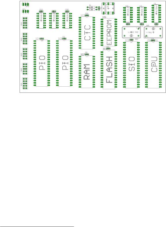
2 |
CHAPTER 1. MICROCONTROLLER BASICS |
memory), and EEPROM (for constants).1 The resulting board layout is depicted in Figure 1.1; as you can see, there are a lot of chips on the board, which take up most of the space (euro format, 10 × 16 cm).
Figure 1.1: Z80 board layout for 32 I/O pins and Flash, EEPROM, SRAM.
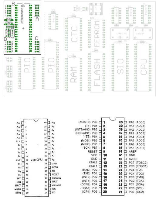
Incidentally, we could also solve the problem with the ATmega16 board we use in the Microcontroller lab. In Figure 1.2, you can see the corresponding part of this board superposed on the Z80 PCB. The reduction in size is about a factor 5-6, and the ATmega16 board has even more features than the Z80 board (for example an analog converter)! The reason why we do not need much space for the ATmega16 board is that all those chips on the Z80 board are integrated into the ATmega16 microcontroller, resulting in a significant reduction in PCB size.
This example clearly demonstrates the difference between microcontroller and microprocessor: A microcontroller is a processor with memory and a whole lot of other components integrated on one chip. The example also illustrates why microcontrollers are useful: The reduction of PCB size saves time, space, and money.
The difference between controllers and processors is also obvious from their pinouts. Figure 1.3 shows the pinout of the Z80 processor. You see a typical processor pinout, with address pins A0- A15, data pins D0-D7, and some control pins like INT, NMI or HALT. In contrast, the ATmega16 has neither address nor data pins. Instead, it has 32 general purpose I/O pins PA0-PA7, PB0-PB7,
1We also added a reset button and connectors for the SIO and PIO pins, but leave out the power supply circuitry and the serial connector to avoid cluttering the layout.
1.1. INTRODUCTION |
3 |
Figure 1.2: ATmega16 board superposed on the Z80 board.
Figure 1.3: Pinouts of the Z80 processor (left) and the ATmega16 controller (right).
PC0-PC7, PD0-PD7, which can be used for different functions. For example, PD0 and PD1 can be used as the receive and transmit lines of the built-in serial interface. Apart from the power supply, the only dedicated pins on the ATmega16 are RESET, external crystal/oscillator XTAL1 and XTAL2, and analog voltage reference AREF.
Now that we have convinced you that microcontrollers are great, there is the question of which microcontroller to use for a given application. Since costs are important, it is only logical to select the cheapest device that matches the application’s needs. As a result, microcontrollers are generally tailored for specific applications, and there is a wide variety of microcontrollers to choose from.
The first choice a designer has to make is the controller family – it defines the controller’s archi-

4 |
CHAPTER 1. MICROCONTROLLER BASICS |
tecture. All controllers of a family contain the same processor core and hence are code-compatible, but they differ in the additional components like the number of timers or the amount of memory. There are numerous microcontrollers on the market today, as you can easily confirm by visiting the webpages of one or two electronics vendors and browsing through their microcontroller stocks. You will find that there are many different controller families like 8051, PIC, HC, ARM to name just a few, and that even within a single controller family you may again have a choice of many different controllers.
Controller |
Flash |
SRAM |
EEPROM |
I/O-Pins |
A/D |
Interfaces |
|
(KB) |
(Byte) |
(Byte) |
|
(Channels) |
|
|
|
|
|
|
|
|
|
|
|
|
|
|
|
AT90C8534 |
8 |
288 |
512 |
7 |
8 |
|
AT90LS2323 |
2 |
128 |
128 |
3 |
|
|
AT90LS2343 |
2 |
160 |
128 |
5 |
|
|
AT90LS8535 |
8 |
512 |
512 |
32 |
8 |
UART, SPI |
AT90S1200 |
1 |
64 |
|
15 |
|
|
AT90S2313 |
2 |
160 |
128 |
15 |
|
|
ATmega128 |
128 |
4096 |
4096 |
53 |
8 |
JTAG, SPI, IIC |
ATmega162 |
16 |
1024 |
512 |
35 |
|
JTAG, SPI |
ATmega169 |
16 |
1024 |
512 |
53 |
8 |
JTAG, SPI, IIC |
ATmega16 |
16 |
1024 |
512 |
32 |
8 |
JTAG, SPI, IIC |
ATtiny11 |
1 |
|
64 |
5+1 In |
|
|
ATtiny12 |
1 |
|
64 |
6 |
|
SPI |
ATtiny15L |
1 |
|
64 |
6 |
4 |
SPI |
ATtiny26 |
2 |
128 |
128 |
|
16 |
SPI |
ATtiny28L |
2 |
128 |
|
11+8 In |
|
|
|
|
|
|
|
|
|
Table 1.1: Comparison of AVR 8-bit controllers (AVR, ATmega, ATtiny).
Table 1.12 shows a selection of microcontrollers of Atmel’s AVR family. The one thing all these controllers have in common is their AVR processor core, which contains 32 general purpose registers and executes most instructions within one clock cycle.
After the controller family has been selected, the next step is to choose the right controller for the job (see [Ber02] for a more in-depth discussion on selecting a controller). As you can see in Table 1.1 (which only contains the most basic features of the controllers, namely memory, digital and analog I/O, and interfaces), the controllers vastly differ in their memory configurations and I/O. The chosen controller should of course cover the hardware requirements of the application, but it is also important to estimate the application’s speed and memory requirements and to select a controller that offers enough performance. For memory, there is a rule of thumb that states that an application should take up no more than 80% of the controller’s memory – this gives you some buffer for later additions. The rule can probably be extended to all controller resources in general; it always pays to have some reserves in case of unforseen problems or additional features.
Of course, for complex applications a before-hand estimation is not easy. Furthermore, in 32bit microcontrollers you generally also include an operating system to support the application and
2This table was assembled in 2003. Even then, it was not complete; we have left out all controllers not recommended for new designs, plus all variants of one type. Furthermore, we have left out several ATmega controllers. You can find a complete and up-to-date list on the homepage of Atmel [Atm].
1.1. INTRODUCTION |
5 |
its development, which increases the performance demands even more. For small 8-bit controllers, however, only the application has to be considered. Here, rough estimations can be made e.g. based on previous and/or similar projects.
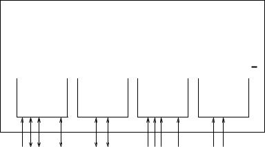
The basic internal designs of microcontrollers are pretty similar. Figure 1.4 shows the block diagram of a typical microcontroller. All components are connected via an internal bus and are all integrated on one chip. The modules are connected to the outside world via I/O pins.
Microcontroller
Processor |
|
SRAM |
|
EEPROM/ |
|
Counter/ |
||||||
|
|
|
Timer |
|||||||||
Core |
|
|
Flash |
|
||||||||
|
|
|
|
|
Module |
|||||||
|
|
|
|
|
|
|
|
|
||||
|
|
|
|
|
|
|
|
|
|
|
|
|
|
|
|
|
Internal Bus |
|
|
|
|
|
|
||
|
|
|
|
|
|
|
|
|
|
|
|
|
Digital I/O |
|
Serial |
|
Analog |
|
Interrupt |
||||||
|
Interface |
|
|
|||||||||
Module |
|
|
Module |
|
Controller |
|||||||
|
Module |
|
|
|||||||||
|
|
|
|
|
|
|
|
|
|
|
||
... |
... |
Figure 1.4: Basic layout of a microcontroller.
The following list contains the modules typically found in a microcontroller. You can find a more detailed description of these components in later sections.
Processor Core: The CPU of the controller. It contains the arithmetic logic unit, the control unit, and the registers (stack pointer, program counter, accumulator register, register file, . . . ).
Memory: The memory is sometimes split into program memory and data memory. In larger controllers, a DMA controller handles data transfers between peripheral components and the memory.
Interrupt Controller: Interrupts are useful for interrupting the normal program flow in case of (important) external or internal events. In conjunction with sleep modes, they help to conserve power.
Timer/Counter: Most controllers have at least one and more likely 2-3 Timer/Counters, which can be used to timestamp events, measure intervals, or count events.
Many controllers also contain PWM (pulse width modulation) outputs, which can be used to drive motors or for safe breaking (antilock brake system, ABS). Furthermore the PWM output can, in conjunction with an external filter, be used to realize a cheap digital/analog converter.
Digital I/O: Parallel digital I/O ports are one of the main features of microcontrollers. The number of I/O pins varies from 3-4 to over 90, depending on the controller family and the controller type.