

60 |
CHAPTER 2. MICROCONTROLLER COMPONENTS |
2.6 Timer
The timer module, which is strictly speaking a counter module, is an important part of every microcontroller, and most controllers provide one or more timers with 8 and/or 16 bit resolution. Timers are used for a variety of tasks ranging from simple delays over measurement of periods to waveform generation. The most basic use of the timer is in its function as a counter, but timers generally also allow the user to timestamp external events, to trigger interrupts after a certain number of clock cycles, and even to generate pulse-width modulated signals for motor control.
2.6.1Counter
Each timer is basically a counter which is either incremented or decremented upon every clock tick. The direction (upor down-counter) is either fixed or configurable. The current count value can be read through a count register and can be set to a specific value by the user. For a timer resolution of n, the count value is within [0, 2n − 1]. Care must be taken when the timer length exceeds the word length of the controller, e.g., when using a 16-bit timer on an 8-bit controller. In such a case, access to the 16-bit count value must be done in two passes, which could lead to inconsistent values. Just think of a timer that is at value 0x00FF and will switch to 0x0100 in the next cycle. If you read the high byte first and the low byte with the next instruction, you will get 0x0000. If you do it the other way round, you will end up with 0x01FF, which is not any better. To counter such problems, the ATmega16 controller uses a buffer register to store the high byte of the timer. So whenever the program reads the low byte of the count register, the high byte is simultaneously stored in the buffer and can then be read at the next cycle. Likewise, to write a new count value, the high byte should be written first (and is stored in the buffer by the controller), and as soon as the low byte is written, both high and low byte are written into the count register in one go.
Timers can generally raise an interrupt whenever they experience an overflow of the count value. This can be used to implement a rudimentary periodic signal by setting the count value to a given start value and then waiting for the overflow. However, this method does not give an accurate period because after the overflow the timer has to be set to its starting value by the program. In consequence, the time from the overflow until the start value has been reloaded into the timer must either be considered and incorporated into the start value, or the period will be longer than desired.
To avoid this drawback, some timers provide a modulus mode which automatically reloads the start value when the timer overflows. Another method for getting accurate periods is to use the output compare feature we will describe shortly.
Although the timer is generally clocked by the same source as the microcontroller itself, this need not be the case. Microcontrollers may allow one or more of the following sources for clocking the timer.
System Clock (Internal Clock)
In this mode, the timer is incremented with every tick of the system clock. This is the default mode. Note that the term “internal” only refers to the fact that this is the clocking source the whole controller uses. The oscillator responsible for it may well be external.
2.6. TIMER |
61 |
Prescaler
This mode also uses the system clock, but filtered through a prescaler. The prescaler is basically just another counter of variable length (8 or 10 bit are typical values), which is incremented with the system clock. The timer itself, however, is clocked by one of the prescaler bits. If, for example, the prescaler is incremented with every rising edge of the system clock, then its lsb will have twice the period of the system clock. Hence, if the timer is clocked with the lsb, this implies a prescale value of 2 and the timer will operate with half the frequency of the system clock. The bit next to the lsb will again divide the frequency by two, and so on. The timer module provides mode bits which allow the user to select some prescale values (8, 64, 256, . . . ).
It is important to realize that although the prescaler is useful to extend the range of the timer, this comes at the cost of coarser timer granularity. For example, if you use an 8-bit timer at 1 MHz, its range will be 255 µs and its granularity will be 1 µs. The same timer, with a prescaler of 1024, will have a range of approximately 260 ms, but its granularity will only be about 1 ms. So a prescaled timer is able to measure longer durations, but the measurement error is larger as well. By the same token, a prescaled timer allows the program to wait for a longer amount of time, but the higher the prescale value, the less likely will the timer be able to wait precisely for a given arbitrary period. As a consequence, it is generally prudent when measuring durations to use the smallest prescaler value that fits the application’s needs to get the best granularity out of the available choices.
Be aware that when you use a prescaler and need to change the timer value, you must decide whether to change the value on the fly or not. As we have explained in Section 2.6.1, writing a new value into the count register of a running timer can be a problem. But even aside from the atomic access issue, prescalers introduce another hazard: When you use a prescaler, you scale down the system clock frequency for the timer. With a prescaler of P , only every P -th tick of the system clock causes a timer tick. Your application, however, is still executed with the system clock frequency, so the code changing the timer value will most likely not coincide with a timer tick, but will be somewhere between two timer ticks. For example, assume that you want to set the timer to value T . You do so at time k · P + x, where x (0, P ) is the offset from the k-th timer tick. The timer will increment the value to T + 1 at time (k + 1) · P , so the first tick will last for x < P system ticks.
|
|
|
|
|
|
|
|
1.75 timer ticks |
|
|
|
|
|
|
|
|
|
|
|
|
2 timer ticks |
|
||||||||||||||||
|
|
|
|
|
|
|
|
|
|
|
|
|
|
|
|
|
|
|
|
|
|
|
|
|
|
|
|
|
|
|
|
|
|
|
|
|
counter value |
|
|
|
|
|
|
|
|
|
|
|
|
|
|
|
|
|
|
|
|
|
|
|
|
|
|
|
|
|
|
|
|
|
|
|
|
|
|
|
|
0 |
1 |
4 |
5 |
counter value |
0 |
1 |
3 |
4 |
5 |
|||||||||||||||||||||||||||||
|
|
|
|
|
|
|
|
|
|
|
|
|
|
|
|
|
timer ticks |
|
|
|
|
|
|
|
|
|
|
|
|
|
|
|
|
|
|
|
|
timer ticks |
|
|
|
|
|
|
|
|
|
|
|
|
|
|
|
|
|
|
|
|
|
|
|
|
|
|
|
|
|
|
|
|
|
|
|
|
|
||
0 |
0 0 0 1 |
3 3 3 4 |
4 4 4 5 |
timestamp |
0 |
0 0 0 1 |
3 3 |
3 3 3 4 |
4 4 4 5 |
timestamp |
||||||||||||||||||||||||||||
|
|
|
|
|
|
|
|
|
|
|
|
|
|
|
|
|
system clock ticks |
|
|
|
|
|
|
|
|
|
|
|
|
|
|
|
|
|
|
|
|
system clock ticks |
|
|
|
|
|
|
|
|
|
|
|
|
|
|
|
|
|
|
|
|
|
|
|
|
|
|
|
|
|
|
|
|
|
|
|
|
|
||
|
|
|
|
|
|
|
|
|
|
|
|
|
|
|
|
|
|
stop timer |
|
|
|
restart timer |
|
|||||||||||||||
|
|
|
|
|
|
|
|
|
|
|
|
|
|
|
|
|
|
|
|
|
|
|||||||||||||||||
|
|
|
|
|
|
|
|
|
|
|
|
|
|
|
|
|
|
|
|
|
|
|||||||||||||||||
|
|
|
|
set timer to 3 |
|
|
|
|
|
|
|
|
|
|
set timer to 3 |
|
|
|
|
|
|
|||||||||||||||||
(a) changing timer value on−the−fly |
(b) changing timer value, restarting timer |
|||||||||||||||||||||||||||||||||||||
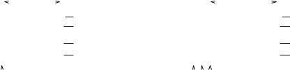
Figure 2.26: Changing the value of a timer (a) on the fly and (b) by stopping and restarting the timer.
This behavior can be both a curse and a blessing. In Figure 2.26, we want to wait for 2 ticks (from 3 to 5). In scenario (a), we change the timer value on the fly, in (b) we stop the timer, change the

62 |
CHAPTER 2. MICROCONTROLLER COMPONENTS |
value, and restart the timer. Obviously, version (b) is better suited to this task, because it makes the first timer tick coincide with the system tick at which the timer is started.
period = 2 |
|
|
period = 3 |
|
|
|
period = 2 period = 3+x |
|
|
|
|
||||||||||||||||||||||||||
|
|
|
|
|
|
|
|
|
|
|
|
|
|
|
|
|
|
|
|
|
|
|
|
x |
|
|
|
|
|
|
|||||||
|
|
|
|
|
|
|
|
|
|
|
|
|
|
|
|
|
|
|
|
|
|
|
|
|
|
|
|
|
|||||||||
|
|
. . . |
|
|
|
|
|
|
|
|
. . . |
|
|
|
|
. . . |
|
|
|
|
|
|
|
|
|
|
|
|
|||||||||
3 |
3 |
3 |
2 |
counter value |
3 |
3 |
2 . . . |
|
2 |
|
counter value |
||||||||||||||||||||||||||
|
|
. . . |
|
|
|
|
|
|
|
|
. . . |
|
|
timer ticks |
|
. . . |
|
|
|
|
|
|
. . . |
|
|
|
|
timer ticks |
|||||||||
|
|
|
|
|
|
|
|
|
|
|
|
|
|
|
|
|
|
|
|
|
|||||||||||||||||
3 |
. . . 4 3 |
3 2 2 3 |
. . . 4 2 |
timestamp |
3 |
. . . 4 3 3 2 2 . . . 4 |
2 |
|
timestamp |
||||||||||||||||||||||||||||
|
|
|
|
|
|
|
|
|
|
|
|
|
|
|
|
system clock ticks |
|
|
|
|
|
|
|
|
|
|
|
|
|
|
|
|
|
|
|
|
system clock ticks |
|
|
|
|
|
|
|
|
|
|
|
|
|
|
|
|
|
|
|
|
|
|
|
|
|
|
|
|
|
|
|
|
|
|
|
|
||
|
|
|
|
|
|
|
|
|
|
|
|
|
|
|
|
|
|
|
|
|
|
|
|
|
|
|
|
||||||||||
|
|
|
|
|
|
|
|
|
|
|
|
|
|
|
|
|
|
stop timer |
|
|
|
|
|
restart timer |
|
||||||||||||
|
|
|
|
|
|
|
|
|
|
|
|
|
|
|
|
|
|
|
|
|
|
|
|
||||||||||||||
|
|
|
|
set timer to 2 |
|
|
|
|
|
|
|
|
|
set timer to 2 |
|
|
|
|
|||||||||||||||||||
(a) changing a period on−the−fly |
(b) changing a period, restarting timer |
||||||||||||||||||||||||||||||||||||
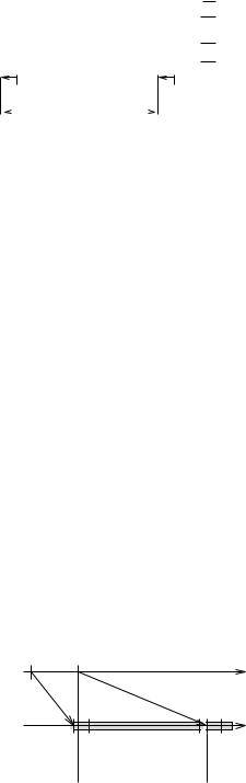
Figure 2.27: Changing the period of a timer in modulus mode (a) on the fly and (b) by stopping and restarting the timer.
In Figure 2.27, we use the timer in a modulus mode to generate a period. The timer is set to a period of 2 (from 3 to including 4), we want to change the period to 3 (from 2 to 4). Again, (a) changes the timer value on the fly whereas (b) stops the timer first. In this case, (a) is better, because the timer keeps running and no time is lost. In version (b), several system ticks are lost due to stopping the timer, so the first interrupt from the new period will be longer.
External Pulse (Pulse Accumulator)
In this mode, the timer gets its clock from an external signal that is connected to a certain input pin of the controller. The timer increments its count value whenever e.g. a rising edge on the input pin is observed. Since the external signal is sampled like any other input signal, the time between edges must be larger than a system clock cycle.
External Crystal (Asynchronous Mode)
Here, the timer is clocked by an external quartz which is connected to two input pins of the controller. This mode is generally designed for a 32.768 kHz watch crystal, which can be used to implement a real-time clock (RTC). The counter is incremented according to the external signal and operates asychronously to the rest of the controller.
2.6.2Input Capture
The input capture feature is used to timestamp (mostly external) events, which may again be rising and/or falling edges, or levels. Whenever the event occurs, the timer automatically copies its current count value to an input capture register, where it can be read by the program. It also sets the input capture flag and can raise an interrupt to notify the application that an input capture event has occured. Microcontrollers may provide one or more pins with input capture functionality.

2.6. TIMER |
63 |
The input capture feature may also be linked to internal event sources. The ATmega16, for instance, can trigger an input capture from its analog comparator module, allowing the application to timestamp changes in the comparator output.
Note that enabling the input capture feature of a pin does not necessarily cause the pin to be set to input. This may still have to be done by the program. In fact, the ATmega16 allows you to use the pin as output and will trigger an input capture if the program generates the appropriate event condition. This can for example be used to measure the delay between an output event and the reaction of the system.
Since the input capture feature is used to timestamp events, it is obvious that this timestamp should be as accurate as possible. As we have explained in Section 2.6.1, the timer has a certain granularity which is affected by the prescaler, and this influences the timestamping accuracy, leading to
tev − tcap (−dinmax, P − 1 − dinmin] |
(2.7) |
clock cycles, where tev is the (real-)time the event occured, tcap is the (real-)time that corresponds to the timestamp the event was timestamped with, dmaxin resp. dminin is the worst case resp. best case input delay (see Section 2.3.1), and P is the prescaler value. Figure 2.28 illustrates the formula.
0 |
1 |
2 |
counter value |
|||||||||
|
|
|
|
|
|
|
|
|
|
|
|
timer ticks |
|
|
|
|
|
|
|
|
|
|
|
|
|
0 |
0 0 0 1 |
1 1 1 2 |
timestamp |
|||||||||
|
|
|
|
|
|
|
|
|
|
|
|
system clock ticks |
|
|
|
|
|
|
|
|
|
|
|
|
|
|
|
|
dinmax |
|
|
dinmin |
|
|||||
Figure 2.28: Minimum and maximum accuracy for a prescaler value of P = 4.
In the figure, it is assumed that an event gets timestamped with 1, so it must have been recognized in one of the system clock cycles where the timestamp was 1. The earliest an event can occur and be timestamped with 1 is dmaxin clock cycles before the first such system clock cycle. The latest an event can occur and still be timestamped with 1 is dminin cycles before the last system clock cycle with timestamp 1. From that, the formula directly follows.
As a consequence, the worst case error (given in clock cycles) when measuring the period between two events is
dinmax + P − 1 − dinmin. |
(2.8) |
Obviously, you should keep the prescaler value as small as possible to obtain the most accurate result.
Finally, it is interesting to know how large the time between two consecutive events can become before we experience an overflow. The largest such interval which will certainly not cause an overflow has the duration
(2r − 1) · P |
(2.9) |
clock cycles, where r is the timer resolution. See Figure 2.29 for an illustration.
64 |
|
|
|
|
|
|
|
|
|
|
|
|
CHAPTER 2. MICROCONTROLLER COMPONENTS |
||||||||||
0 |
1 |
2 |
3 |
0 |
counter value |
||||||||||||||||||
|
|
|
|
|
|
|
|
|
|
|
|
|
|
|
|
|
|
|
|
|
|
|
timer ticks |
|
|
|
|
|
|
|
|
|
|
|
|
|
|
|
|
|
|
|
|
|
|
|
|
0 |
0 0 0 1 |
1 1 1 2 |
2 2 2 3 |
3 3 3 0 |
timestamp |
||||||||||||||||||
|
|
|
|
|
|
|
|
|
|
|
|
|
|
|
|
|
|
|
|
|
|
|
system clock ticks |
|
|
|
|
|
|
|
|
|
|
|
|
|
|
|
|
|
|
|
|
|
|
|
|
|
|
|
|
dinmin |
longest duration |
|
|
|
dinmin |
|
|||||||||||||
Figure 2.29: Maximum time between two events that can be measured without an overflow. Prescaler value P = 4, timer resolution r = 2.
Apart from these formulas, there is another interesting thing about input capture that you should be aware of, and this has to do with how and when the input capture register is read. As we have explained, the timestamp is stored in the input capture register when the event occurs, and most likely an ISR will be called to read this register. However, raising an interrupt takes several cycles, so it can happen that another input capture event occurs in this period. This second event will again cause the current timestamp to be stored in the input capture register, effectively overwriting the old value. The ISR, which was triggered by the first event, will then read the timestamp of the second event.
This is of course not really a problem yet, since all that happens is that you miss the first event and react to the second one. The real problem lies with microcontrollers that clear the IF bit automatically before executing the ISR. In this case, the second event may occur after the input capture IF has been cleared but before the ISR has read the input capture register. The second event will set the IF again and will overwrite the input capture register, so the ISR will read the timestamp of the second event. However, since the second event also sets the IF anew, as soon as the ISR is finished, it will be called again, this time to serve the second event, and will read the same timestamp as before. So as a result, you have reacted to both events, but have erroneously attributed the second event’s timestamp to both events, see Figure 2.30.
ev1 |
ev2 |
|
|
TS1 |
TS2 |
t |
|
|
|
|
|
call ISR |
read TS2 |
readtTS2 |
|
clear IF |
instead TS1 |
|
|
set IF |
call ISR |
||
ICR = TS(ev2)! |
|
||
Figure 2.30: Both calls to the ISR read the timestamp of the second event.
There is not much you can do against this problem if it can occur, exept read the input capture register as soon as possible. You may also check whether successive timestamps are equal and in that case discard the first one. If you use a controller that allows (or even requires) you to set back the IF,