

2.6. TIMER |
65 |
set it back after you have read the capture register. This will still cause you to lose events, though. Your best protection is to make sure that such events do not occur too close together. So the minimum interval between events should be larger than the interrupt latency plus the time until you read the capture register.
Like external interrupts in general, input capture suffers from noisy input signals. Hence, many controllers offer noise cancellation, which is generally implemented as outlined in Section 2.3.1 (several samples are taken and compared).
2.6.3Output Compare
The output compare feature is the counterpart to the input capture. For the latter, the timestamp gets stored whenever something interesting happens on the input line. With output compare, something happens on an output line when a certain time is reached. To implement this feature, the timer offers an output compare register, where you can enter the time at which the output compare event should happen. Whenever the counter value reaches this compare value, the output compare event is triggered. It can automatically set or clear an output line, or even toggle its state. It can also do nothing and simply raise an internal interrupt.
Output compare often comes with a reset option, which automatically resets the counter when the compare value is reached. This allows to set up a periodic interrupt (or output signal) with a minimum of effort.
2.6.4Pulse Width Modulation
The pulse width modulation (PWM) mode is a special case of the output compare. In it, the timer generates a periodic digital output signal with configurable high-time and period. Two registers form the main interface to the PWM, one for the period (also called duty cycle) and one for the high-time (or the low-time). Some timers only allow the user to configure the high-time, and either use the full timer range as the period or offer a restricted choice of possible periods. In addition to these registers, the timer module provides bits to enable PWM and possibly for mode control.
PWM signals are useful for a lot of things. Apart from their uses in simple d/a converters they can be used e.g. to implement ABS in cars, to dim LEDs or numeric displays, or for motor control (servos, stepper motors, speed control of dc motors).
The internal realization of PWM is actually quite simple and just uses the counter and two compares. There are two possible implementations, one using an up-counter (or down-counter) and one using an up-down counter. In the following explanations, we will assume that the user specifies the high time of the signal, which we will call the compare value, and that the period is given by the top value.
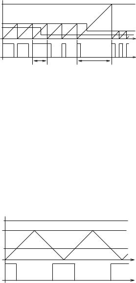
In the up-counter version, see Figure 2.31, the output is set to high when the counter reaches zero, and it is set to low when the counter reaches the compare value. As soon as the top value is reached, the counter is reset to zero. The advantage of this method is its resource-efficiency. However, if you can update the compare and top values anytime within the duty cycle, you can produce glitches in the PWM signal, which are invalid interim cycles. For example, if you set the top value below the current count value, the timer will count through its full range once before switching to the correct duty cycle.
66 |
CHAPTER 2. MICROCONTROLLER COMPONENTS |
|
maximum counter value |
|
|
update |
update |
top |
cmp |
top |
cmp |
|
t |
PWM |
|
|
|
|
|
output |
|
t |
|
|
|
|
glitch |
glitch |
Figure 2.31: PWM signal generated by an up-counter and the results of unbuffered updates.
Controllers which use this method may hence only take over new top and compare values when the counter reaches zero. If you set the compare value above the top value, the output will be constantly high.
In the up-down-counter version, see Figure 2.32, the counter first counts up from zero to the top value and then switches direction and counts down back to zero. The counter starts by setting the output to high and begins counting at zero. Whenever the compare value is reached on the upcount, the output is set to low. When the compare value is reached again on the downcount, the output is set back to high. As you can see, this results in a nice symmetrical signal with a period that can be twice as long as that of a pure up-counter. Again, asynchronous updates of the compare or top value can result in glitches, so the controller must buffer the values until zero is reached.
|
maximum counter value |
|
top |
|
|
cmp |
t |
|
PWM |
||
|
||
output |
t |
|
|
Figure 2.32: PWM signal generated by an up-down-counter.
In both versions, the attainable period is determined by the resolution of the timer. If the high time is set to zero or to (or above) the top value, this will generally result in a constant low or high signal.
2.6.5Exercises
Exercise 2.6.1 You only have two 8-bit timers on your 8-bit microcontroller but want to have a 16-bit timer for your application. Can you solve this problem in software? How does your solution work? What functions do you have to provide as an API (application program interface) to your timer? Do you have to think about asynchronous updates?
Exercise 2.6.2 Assume that your microcontroller has an operating frequency of 1 MHz and two timers, an 8- and a 16-bit timer. It is your task to select useful prescaler modes for the timers. Each
2.6. TIMER |
67 |
timer can have four such modes between 2 and 1024 (and the values must be powers of 2). Which prescaler modes would you assign and why?
Exercise 2.6.3 Assume that your microcontroller is clocked with 4 MHz and that it offers an 8-bit timer operating with this frequency. You want to use this timer to measure the duration between two external events. What bounds does this impose on the duration (minimum and maximum interval). How large is your measurement error? How does a prescale value of 256 affect your answers?
Exercise 2.6.4 If compare and top value updates are not buffered, how many different ways are there to produce a glitch when using an up-down-counter to generate a PWM signal? Give an example for each way you find. How would you solve the update problem? What if the controller can raise an interrupt whenever the PWM signal reaches zero?
Exercise 2.6.5 You want to measure the period of a periodic digital signal and decide to use the external event counter (pulse accumulator) for this purpose. Sketch how you can measure the period this way. How accurately can you measure the period? Compare this method to a solution with input capture.