

Industrial Control (Students guide, 1999, v1.1 )
.pdfExperiment #7: Real-time Control and Data Logging
Questions and Challenges:
1)The time data stored in the DS1302 uses the ______ number system.
2)Add a temperature setting of 95 F to be enabled between 4:00PM (16:00) and 6:00 PM (18:00). Modify the starting time and initial temperature to test both times.
3)Use the LED on P8 to simulate a house lamp. Add code to energize it at 8:00 PM (20:00) and de-energize it at 11:00 PM (23:00). Modify the starting time of RTC to test both times.
Exercise #2: Interval Timing
Instead of having events occur at defined times of the day, often a process may need to perform actions at certain intervals of time. The annealing process is one such process. In this example a metal is heated at a given temperature for a set amount of time, raised to another temperature for a set amount of time, and then cooled to yet another temperature. This tempers the metal and gives it certain desirable characteristics, such as hardness and tensile strength.
Since we are dealing with intervals of time instead of absolute times, we will need to perform calculations to find the target time that marks the end of an interval. The time interval must be added to the start time of the temperature phase. This sounds simple, but it isn’t.
If you remember, our time keeping is performed in BCD, a subset of hexadecimal. When adding values together for time, the BASIC Stamp 2 is working in hexadecimal. Take the example of 38 seconds + 5 seconds. We know this should yield a result of 43 seconds, but since we are really adding $38 + $05 (hexadecimal), our result is $3D (counting 5: $39, $3A, $3B, $3C, $3D). If we compare that value to a time from the RTC, it will never occur!
We need to decimal adjust the result. This is done by checking whether the digit exceeds the legal BCD range ( >9) and adding 6 if it does. Test this with the above result:
$3D + $06 = $43 (counting 6: $3E, $3F, $40, $41, $42, $43). Success! We now have the result we needed for BCD values.
Some other issues we need to contend with is that either the one's or ten's place may need to be adjusted. Depending on the result we may need to carry over into our minutes or hours. Seconds and minutes need to roll over at 60, while hours needs to roll over at 24.
Industrial Control Version 1.1 •Page 199

Experiment #7: Real-time Control and Data Logging
This is the general sequence, or algorithm, our program will use:
•Check whether the one's place in seconds is legal BCD (<$A). No: Add 6 to seconds.
•Check whether the seconds exceeded <60.
No: Subtract 60 from seconds. Add one to minutes.
• Check whether the one's place in minutes is legal BCD (<$A). No: Add 6 to minutes
Here’s the code:
AdjustTime: 'BCD Time adjust routine
IF Cseconds.lownib < $A THEN HighSec
Cseconds = Cseconds + 6
HighSec:
If Cseconds < $60 Then LowMin
Cseconds = Cseconds - $60
Cminutes = Cminutes + 1
LowMin:
IF Cminutes.lownib < $A THEN HighMin
Cminutes = Cminutes + 6
HighMin:
IF Cminutes < $60 THEN LowHours
CMinutes = Cminutes - $60
Chours = Chours + 1
LowHours:
IF CHours.lownib < $A THEN HighHours
Chours = Chours + 6
HighHours:
IF Chours < $24 THEN AdjustDone
Chours = Chours - $24
AdjustDone:
RETURN
There is one case where this algorithm won't provide the correct results: When we add a value greater than 6 in any position when the place exceeds 7. Take the example of $58 + $08. Adding in hex we get $60. This returns a valid BCD number, just not one that is computationally correct for BCD. An easy fix for adding 8, is to add 4, adjust, then add 4 more and adjust again. Easier yet would be to not choose timing intervals containing the digits 7, 8, or 9!
In this section we will simulate this process with our incubator, but keep in mind annealing typically heats in thousands of degrees. This is the sequence our annealing process will follow:
•Phase 1: Heat at 95.0 F for 5 minutes.
•Phase 2: Heat to 100 F for 15 minutes.
Page 200 •Industrial Control Version 1.1

Experiment #7: Real-time Control and Data Logging
•Phase 3: Cool to 85.0 F for 10 minutes.
•Process complete, start over for next material sample.
Make the following changes/additions to program 7.1 for Program 7.2.
'Program 7.2: Interval Timing
'Controls temperature at 3 levels for set amount of time
'****** Initialize Settings ***** |
' |
Time to set clock |
||
Time |
= |
$1200 |
||
Seconds |
= |
$00 |
|
|
PTemp1 |
CON |
950 |
' |
1st phase temperature |
PTemp2 |
CON |
1000 |
' |
2nd phase temperature |
PTemp3 |
CON |
850 |
' |
3rd phase temperature |
PTime1 |
CON |
$05 |
' |
Do not use digits 7 or above |
' |
Length of phase 1 |
|||
PTime2 |
CON |
$15 |
' |
Length of phase 2 |
PTime3 |
CON |
$10 |
' |
Length of phase 3 |
'******************************* |
|
|
||
Gosub SetTime |
|
' |
Set clock (Remark out once set) |
|
Setpoint = PTemp1 |
' |
Initial setpoint to 1st phase temp |
||
Gosub ReadRTCBurst |
' |
Get clock reading |
||
CTime = Time |
|
' |
Set Change time to current |
|
CMinutes = Minutes + PTime1 |
' |
Add Phase 1 time |
||
Gosub AdjustTime |
' |
BCD adjust time |
||
' Define A/D constants & variables |
|
|
||
(Middle section of code remains unchanged) |
|
|
||
|
|
|
|
|
TimeControl: |
|
' |
Check if ready for change |
|
|
IF (Time = CTime) AND (Setpoint = PTemp3) THEN |
Phase1 |
||
|
IF (Time = CTime) AND (Setpoint = PTemp1) THEN |
Phase2 |
||
|
IF (Time = CTime) AND (Setpoint = PTemp2) THEN |
Phase3 |
||
|
Return |
|
|
|
Phase1: |
Debug "Phase 3 Complete - Next Sample",CR |
' |
Phase 1 - Set for phase 1 |
|
|
|
|
||
|
Debug "!BELL",CR |
|
|
|
|
Setpoint = PTemp1 |
|
|
|
|
Cminutes = Cminutes + PTime1 |
|
|
|
|
GOTO SetNext |
|
|
|
Phase2: |
DEBUG "Phase 1 Complete",CR |
' |
Phase 2 - Set for phase 2 |
|
|
|
|
||
|
Setpoint = PTemp2 |
|
|
|
Industrial Control Version 1.1 •Page 201

Experiment #7: Real-time Control and Data Logging
Cminutes = Cminutes + PTime2
GOTO SetNext
Phase3: |
|
|
' Phase 3 - Set for phase 3 |
|
DEBUG "Phase 2 Complete",CR |
||
|
Setpoint |
= |
PTemp3 |
|
Cminutes |
= |
Cminutes + PTime3 |
SetNext:
GOSUB AdjustTIme ' BCD adjust time DEBUG "Time: ", hex2 hours,":",hex2 minutes,":",hex2 seconds DEBUG "-- Setpoint: ", dec setpoint,cr
RETURN
AdjustTime: |
'BCD Time adjust routine |
IF Cseconds.lownib < $A THEN HighSec
Cseconds = Cseconds + 6
HighSec:
If Cseconds < $60 Then LowMin
Cseconds = Cseconds - $60
Cminutes = Cminutes + 1
LowMin:
IF Cminutes.lownib < $A THEN HighMin
Cminutes = Cminutes + 6
HighMin:
IF Cminutes < $60 THEN LowHours
CMinutes = Cminutes - $60
Chours = Chours + 1
LowHours:
IF CHours.lownib < $A THEN HighHours
Chours = Chours + 6
HighHours:
IF Chours < $24 THEN AdjustDone
Chours = Chours - $24
AdjustDone:
RETURN
Page 202 •Industrial Control Version 1.1
Experiment #7: Real-time Control and Data Logging
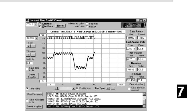
Figure 7.5: Interval Timer Plot
Figure 7.5 is a screen shot of a sample run. Notice there is 3 distinct temperature phases, and then it repeats. Download and run program 7.2. Use StampPlot Lite to monitor your system.
Questions and Challenges:
1) Why is using the RTC preferable for long-interval timing instead of PBASIC Pause commands?
2) Add the following hexadecimal values and decimal adjust the results (show work): $15 + $15
3) Modify the program to add a 5-minute phase 4 at 80.0 F.
Industrial Control Version 1.1 •Page 203

Experiment #7: Real-time Control and Data Logging
Exercise #3: Data Logging
Data logging does not fall into the area of process-control, but it is an important subject, and since the RTC is connected, this is an appropriate time to discuss it. The majority of our experiments have used StampPlot Lite to graphically display current conditions in our system. Of course, one of the biggest benefits of microcontrollers are that they are self-contained and do not require a PC. All the experiments in this text would operate properly whether the data was being plotted on a PC or not. We simply wouldn't have any direct feedback of the status.
Data logging is used to collect data and store it locally by the microcontroller. This data may then be downloaded later for analysis. Some examples of this include remote weather stations and Space-Shuttle experiments. Due to location or other factors, it may not be practical to be collecting data on a PC in real time.
When data is logged to memory, it is important to make sure the hardware, programming, and time keeping is as stable as possible. The data-logger may not be accessed for very long periods of time. Unintentionally resetting the Stamp will usually lose your data and start the programming over. The Stamp is easily reset by pressing the reset button, by connecting it to a computer sometimes, or possibly even a temporary loss power.
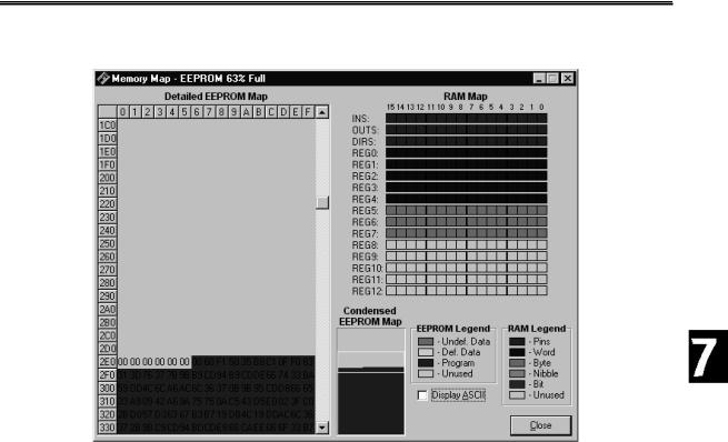
Just as BASIC Stamp programs are stored in non-volatile memory (remains with loss of power) in EEPROM, we may also write data directly into the EEPROM. The BASIC Stamp 2 has 2048 bytes of available EEPROM memory for program and data storage. Figure 7.6 shows the BASIC Stamp 2 memory map. Programs are stored at the end of memory, allowing us to use the top of memory for data.
Page 204 •Industrial Control Version 1.1
Experiment #7: Real-time Control and Data Logging
Figure 7.6: BASIC Stamp 2 Memory Map
When data is logged, we will need to retrieve from the unit both the value and time that a reading was recorded. In recording the data, the time of the data may be recorded into memory along with the value. This would require 3 bytes to be used for each measurement: Hour, Minute and Value (optionally, the second may be recorded depending on the need). Or, we can record the time that the data recording commenced or started; storing only the data at a known interval the program can then extrapolate the time of each measurement. This only requires 1 byte per measurement for the value with a one-time recording of the start time.
But what happens if the controller is inadvertently reset, such as when connecting it to the computer for the data dump? What would happen if the start time or the current log sample location were lost? What if the RTC was reset at some point so the time clock was reset? We can also use the EEPROM to keep track of important data, such as the start time and next memory location in the event the controller is reset preventing important data from being lost. The program we have developed helps to ensure data is not lost on inadvertent resets.
Industrial Control Version 1.1 •Page 205

Experiment #7: Real-time Control and Data Logging
A power outage is one eventuality our program will not deal with. Upon power loss, the BS2 will be able to recover current data, but the RTC will probably contain non-valid times. Some possible fixes for this are running the project off a battery, or adding a high-capacity capacitor to the RTC as per the data sheets. A ‘super-cap’, a gold-plated capacitor can maintain the RTC time for many hours or even days. One other option may be to continually write the current time to EEPROM so that in the event power is lost, the most recent time may be written back to the RTC. But EEPROMs have limited write-cycles. After several thousand writes the EEPROM will eventually fail, so we may not want to repeatedly write to the same location.
How much data can we hold? After the program is downloaded, there is approximately 700 bytes left of the original 2K of EEPROM in the BASIC Stamp 2. This will allow us to store 700 logged pieces of data. At 5- minute intervals, how long could we store data before memory is full? Some other options for storing data may be on the RTC in general user registers, or on a separate device, such as a serial EEPROM.
Note: Do not log more data than the EEPROM has room for – overwriting code space will cause the BASIC Stamp program to fail!
The WRITE command is used to write data into memory:
WRITE Memory Address, byte value
The READ command is used to read data from memory into a variable:
READ Memory Address, byte variable
We will use the DS1302 as an interval timer that will control when samples are taken. For this experiment we will collect outside temperature over a long period of time and then download the results to StampPlot Lite.
Program 7.3 is the code for our data logger. It is sufficiently different from our other programs to require a full listing though much of the code can be re-used.
'Program |
7.3 - |
Real Time Data Logging |
|
temperature |
||
'This program will record in EEPROM memory the |
||||||
'at the specified intervals using the real time clock. |
||||||
'*** Set |
Init. Time and Logging Interval ************** |
|||||
Time |
= |
|
$2246 |
|
' |
Initialization Time |
' Do not |
use digits > 6 |
' |
Sample interval (in BCD minutes) for logging |
|||
Interval |
|
CON |
$05 |
|||
Samples CON |
500 |
0 |
' |
Number of samples to acquire |
||
Stop_Reset |
CON |
' |
When full, 0=reset, 1 = stop logging |
|||
'******************************************************
Page 206 •Industrial Control Version 1.1

Experiment #7: Real-time Control and Data Logging
'Define RTC Constants 'Register values in the RTC
SecReg |
CON |
%00000 |
MinReg |
CON |
%00001 |
HrsReg |
CON |
%00010 |
CtrlReg |
CON |
%00111 |
BrstReg |
CON |
%11111 |
'Constant for BS2 Pin connections to RTC
RTC_CLK |
CON |
12 |
RTC_IO |
CON |
13 |
RTCReset |
CON |
14 |
'Real Time variables |
BYTE |
|
RTCCmd |
VAR |
|
RTemp |
VAR |
BYTE |
' Current Time |
Variables |
|
Time |
VAR |
WORD |
Hours |
VAR |
Time.HIGHBYTE |
Minutes |
VAR |
Time.LOWBYTE |
Seconds |
VAR |
BYTE |
' Log-Time variables |
WORD |
|
LTime |
VAR |
|
LHours |
VAR |
LTime.HIGHBYTE |
LMinutes |
VAR |
LTime.LOWBYTE |
LSeconds |
VAR |
BYTE |
' Start time variables |
WORD |
|
STime |
VAR |
|
SHours |
VAR |
STime.HIGHBYTE |
SMinutes |
VAR |
STime.LOWBYTE |
MemAddr VAR |
WORD |
|
' Define A/D constants & variables |
||
CS |
CON |
3 |
CLK |
CON |
4 |
Dout |
CON |
5 |
Datain |
VAR |
BYTE |
Temp |
VAR |
WORD |
TempSpan |
CON |
5000 |
Offset |
CON |
700 |
DIR15 = 0 |
|
|
DIR8 = 1 |
VAR |
IN15 |
PB |
||
LED |
CON |
8 |
LOW LED |
|
|
'***** Initialize *******
'Current memory location for storage
'0831 chip select active low from BS2 (P3)
'Clock pulse from BS2 (P4) to 0831
'Serial data output from 0831 to BS2 (P5)
'Variable to hold incoming number (0 to 255)
'Hold the converted value representing temp
'Full Scale input span (5000 = 50 degrees span)
'Minimum temp. Offset. (700 = 70 degrees)
'Pushbutton
'LED
'LED off
Industrial Control Version 1.1 •Page 207

Experiment #7: Real-time Control and Data Logging
INIT:
' To set the new time, hold down PB until LED goes off
DEBUG |
"Hold button now to initialize clock and logging",cr |
||
HIGH 8 |
2000 |
' |
LED On |
PAUSE |
' |
If PB not pressed, don’t store time or restart |
|
IF PB |
= 1 THEN SkipSet |
||
Seconds = $00 |
|
|
|
GOSUB |
SetTime |
|
|
GOSUB |
RecoveryData |
|
|
DEBUG |
"Release button",CR |
|
|
SkipSet: |
|
' |
LED OFF |
LOW LED |
|||
IF PB |
= 0 THEN SkipSet |
' |
Wait for PB release |
READ 0,MemAddr.HIGHBYTE |
' |
Read recovery data of memory address and time |
|
READ 1,MemAddr.LOWBYTE |
|
|
|
READ 2,SHours |
|
|
|
Read 3,SMinutes |
|
|
|
' Initialize time keeping variables |
' |
Read current time |
|
GOSUB |
ReadRTCBurst |
||
LHours = Hours |
' |
Set change hours to current |
|
LMinutes = Minutes |
' |
Set change minutes to current |
|
LSeconds = $00 |
' |
Set change seconds to 00 |
|
LMinutes = LMinutes + Interval |
' |
Add interval to get first log time |
|
GOSUB |
AdjustTime |
' |
Decimal adjust new time |
'***** Main Loop ******* |
|
|
|
Main: |
500 |
|
|
PAUSE |
|
|
|
GOSUB |
Control |
|
|
GOSUB |
Getdata |
|
|
GOSUB |
Calc_Temp |
|
|
GOSUB |
ReadRTCBurst |
|
|
GOSUB |
Display |
|
|
GOSUB |
TimeControl |
|
|
GOTO Main |
|
|
|
Getdata: |
|
' |
Acquire conversion from 0831 |
LOW CS |
|
' |
Select the chip |
LOW CLK |
' |
Ready the clock line. |
|
SHIFTIN Dout, CLK, MSBPOST,[Datain\9] ' |
Shift in data |
||
HIGH CS |
' |
conversion |
|
RETURN |
|
|
|
Calc_Temp: |
|
' |
Convert digital value to |
Temp = TempSpan/255 * Datain/10 + Offset ' temp based on Span & |
|||
RETURN |
|
' |
Offset variables. |
Control: |
= 0 THEN DumpData |
' |
If PB pressed, plot recorded data |
IF PB |
|
|
|
Page 208 •Industrial Control Version 1.1