

Industrial Control (Students guide, 1999, v1.1 )
.pdfExperiment #2: Digital Input Signal Conditioning
Table 2.2 shows the schematic representation of various industrial switches. The symbols are drawn to represent the switch’s “normal” state. Normal state refers to the unactuated or rest state of the switch. The pushbutton switches in this exercise kit are Normally Open (N.O.). Pressing the pushbutton results in a plunger shorting the contacts. The resistance goes from its open value of nearly infinite ohms to a value very near zero. A similar mechanism produces a like action in a Normally Open limit switch.
Table 2.2: Schematic Representation of Various Industrial Switches
While the concept of the switch is simple, there seems to be no limit to the physical design of switches that you will find in industrial control applications. Switches also may be designed as Normally Closed (N.C.); they are closed when at rest and actuation causes their contacts to open. As a technician, programmer, or system designer, you must be aware of the Normal (resting) position of a switch.
Industrial Control Version 1.1 •Page 29
Experiment #2: Digital Input Signal Conditioning
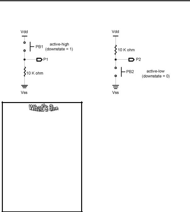
Figure 2.2: Schematic Representation of Pushbutton Switches
Figure 2.2a
Digital Input (TTL, CMOS, ECL, etc.)?
Logic devices are built with a variety of processes that operate at different voltages. The manufacturer’s datasheet will list several critical values for each device. Absolute Maximum Ratings are voltages and currents which must not be exceeded to avoid damaging or destroying the chip. I/O pins on the BASIC Stamp II should not exceed 0.6 V or Vdd+0.6 V (5.6V) with respect to Vss.
The logic transition between high and low is specified in the DC characteristics of the datasheet. A voltage of 0.2 Vdd (1 V on the BASIC Stamp II) is guaranteed to be low, and which 0.45 Vdd (2.25 V) or higher is guaranteed to be high. There is a gray area between these two voltages where the actual transition will occur. It is dependant on temperature and supply voltages where the actual transition will occur. It also varies with temperature and supply voltage but will normally occur at about 1.4 volts.
Figure 2.2b
The input pins of the BASIC Stamp do not detect “changes in resistance” between the switch’s contacts. These inputs expect appropriate voltage levels to represent a logic high or a logic low. Ideally, these levels would be +5 volts for a logic high (1) and 0 volts for a logic low (0).
To convert the two resistive states of the switch into acceptable inputs, it must be placed in series with a resistor across the +5 volt supply of the BASIC Stamp. This forms a voltage divider circuit in which the resistive status of the switch is compared to the resistive value of the reference resistor. Figure 2.2 shows the two possibilities for our simple N.O. pushbutton switch. Figure 2.2a will result in +5 volts being fed to the input pin when it is pressed. When the switch is open, there is no continuity; therefore, no current flows through the 10K resistor and the input pin is grounded.
Page 30 •Industrial Control Version 1.1
Experiment #2: Digital Input Signal Conditioning
Reference Resistor:
The 10K-ohm fixed resistor in Figures 2.2a and 2.2b is required to get dependable logic levels. It is wired in series with the switch. Its value must be much greater than the closed resistance of the switch and much less than its open resistance. When the switch is open in Figure 2.2a, the resistor gets no voltage and the input point is “pulled down” to ground. In Figure 2.2b, the open switch causes the input to be “pulled up” to +5 volts. You must consider the use of pullup and pull-down resistors when working with all mechanical switches and some electronic switches.
In Figure 2.2b, the switch closure results in grounding of the input pin. Zero volts is a logic low. When the switch is opened, there is again no voltage drop across the 10K-ohm resistor and the voltage at the input is +5, a logic high. The circuits are essentially the same, although the results of pressing the switch are exactly opposite. From a programming standpoint, it is important to know with which configuration you are dealing.
Industrial Control Version 1.1 •Page 31
Experiment #2: Digital Input Signal Conditioning
Exercises
Exercise #1: Switch Basics
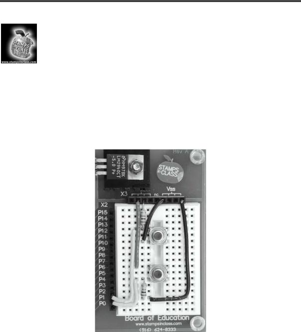
To begin an investigation of programming for simple switch activity, wire the two pushbutton switches shown in Figure 2.2 onto the Board of Education breadboard. Connect the active-high configuration (Figure 2.2a) to I/O Pin 1 and the output of the active-low configuration (Figure 2.2b) to Pin 2. Note which one is which. As stated earlier, this is important. Figure 2.3 shows a pictorial of how the circuit is built on the Board of Education.
Figure 2.3: Pictorial of Parts Layout for circuits of Figure 2.2
Page 32 •Industrial Control Version 1.1

Experiment #2: Digital Input Signal Conditioning
The following program is written to use the StampPlot Lite interface for displaying the status of the switches. The procedure will be the same as you followed in Experiment #1, Flowcharting and StampPlot Lite. First, enter Program 2.1. You may omit from the program all comments which include the apostrophe (‘) and the text that follows.
'Program. 2.1: Switch Level Detection with StampPlot Lite Interface
DEBUG "!TITL Pushbutton Test",CR |
|
' Titles |
the StampPlot screen |
||
INPUT 1 |
|
|
|
' Set P1 |
as an input |
INPUT 2 |
IN1 |
|
|
' Set P2 |
as an input |
PB1 VAR |
|
|
|
|
|
PB2 VAR |
IN2 |
|
|
|
|
Loop: |
100 |
|
|
' Slow the program loop |
|
PAUSE |
|
|
|||
DEBUG |
IBIN PB1, BIN PB2, CR |
|
|
' Plot the digital status |
|
DEBUG |
DEC 0, CR |
|
|
' Output |
a 0 to allow for screen shift |
IF (PB1 = 1) and (PB2 = 0) THEN Both |
' Test for both pressed |
||||
IF PB1 = 1 THEN PB1_on |
|
|
' Test if active-high PB1 is pressed |
||
IF PB2 = 0 THEN PB2_on |
|
|
' Test if active-low PB2 is pressed |
||
DEBUG "!USRS Normal states |
- Neither pressed", CR |
none pressed |
|||
GOTO Loop |
|
|
' Report |
||
|
|
|
|
||
PB1_on: |
"!USRS Input 1 is High |
|
|
' Report |
PB1 pressed |
DEBUG |
|
- PB1 is pressed ", CR |
|
||
GOTO Loop |
|
|
|
|
|
PB2_on: |
"!USRS Input 2 is Low |
|
|
' Report |
PB2 pressed |
DEBUG |
|
- PB2 is pressed ", CR |
|
||
GOTO Loop |
|
|
|
|
|
Both: |
|
|
|
' Report |
both pressed |
DEBUG |
"!USRS PB1 High & PB2 Low - Both pressed", CR |
|
|||
DEBUG |
"!BELL", CR |
|
|
' Sound the bell. |
|
GOTO Loop
Industrial Control Version 1.1 •Page 33
Experiment #2: Digital Input Signal Conditioning
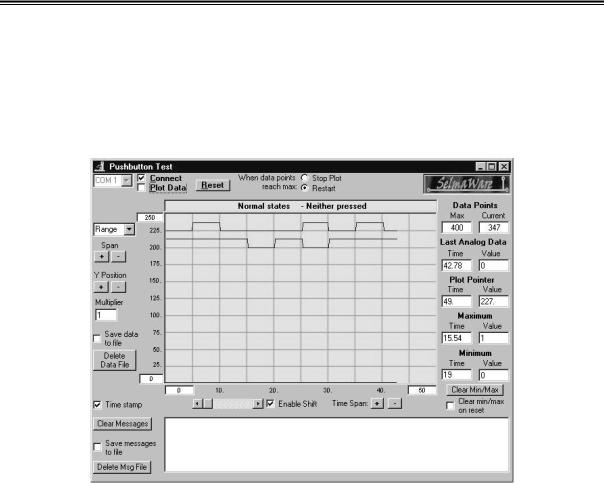
Run the program. DEBUG will scroll the switch status and the input’s digital value. Close the debug screen and open StampPlot Lite. Select the appropriate COM port and check the Connect and Plot Data boxes. Press the reset switch on your Board of Education and the trace of In1 and In2 should start across the screen. Your display should look similar to Figure 2.4. Press the pushbuttons and become familiar with the operation of your system. Next, we will look at how the program works.
Figure 2.4: Typical Screen Shot of StampPlot Monitoring the Status of Pushbuttons
The purpose of this program is to run code based on the pressed or not-pressed condition of the two pushbuttons. This simple exercise gives insight to several considerations when dealing with digital inputs, programming multiple if-then statements, and using some of the PBASIC logical operators.
First, the statements in1 and in2 simply return the logic value of the input pins: +5 V = logic 1 and 0 V = logic 0. The active-high PB1 returns a 1 if pressed. The active-low PB2 returns a 0 when it is pressed. The program is testing for the “logical” status of the inputs; as the programmer, you must understand how this correlates to the “pressed” or “not pressed” condition of the pushbuttons involved. This is evident in the first line of the program loop where the logic operator AND is being used.
Page 34 •Industrial Control Version 1.1
Experiment #2: Digital Input Signal Conditioning
When you consider our switch configurations, it makes logical sense that if In1 returns a logic high and In2 returns a logic low then both switches are pressed. Output actions of industrial controllers often are dependent upon the status of multiple switches and contacts. A review of the PBASIC logical operators, including AND, OR, XOR, and NOT, can provide useful tools in meeting these requirements using the BASIC Stamp.
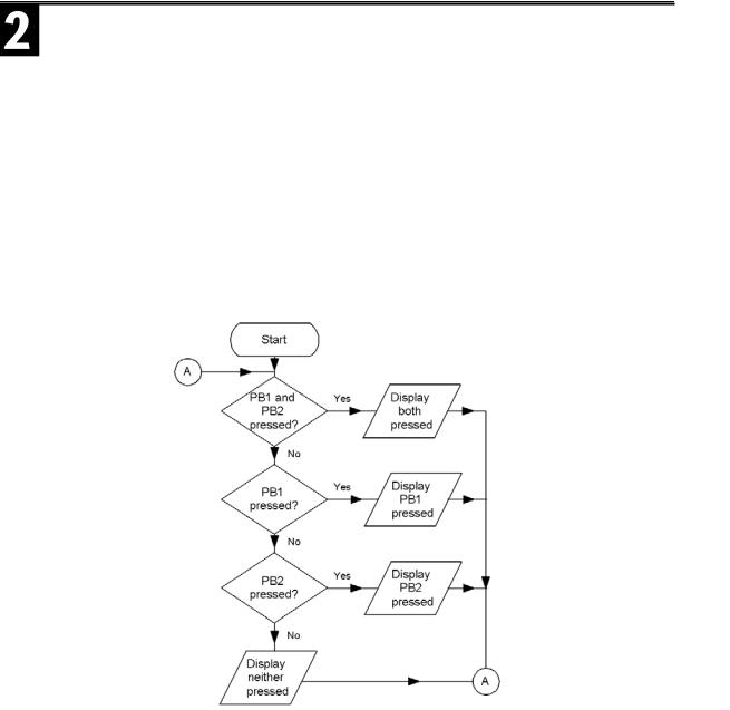
Another aspect of Program 2.1 is to notice the flow of the program loops. The IF-THEN structures test for a condition and if the condition is met, THEN the program execution is passed to the label. In this case, the label routine simply prints the conditions of the switches to the StampPlot Lite Status box. In industrial applications, this portion of the program would cause the appropriate output action to occur. Since the last line of each label is GOTO Loop, program execution returns to the top of the loop and any code below that IF-THEN statement is circumvented. The flowchart in Figure 2.5 shows how the program executes.
Figure 2.5: Flowchart for Program 2.1
Industrial Control Version 1.1 •Page 35

Experiment #2: Digital Input Signal Conditioning
If both switches are pressed, “IF (PB1 = 1) and (PB2 = 0)” is true. Program execution then would go to the Both label. The “both pressed” condition would be indicated in the User Status Bar and your computer bell would ring. After this, program execution is instructed to go back to Loop and test the switches again. As long as both switches remain pressed, the result of this test is continually true and looping is occuring only within this part of the program.
If either or both switches become not pressed, the next three lines of code will do a similar test for the condition.
Pressing PB1 results in “IF PB1 = 1” being true, execution is passed to the PB1 label action, and a return to the top of the loop; “IF PB2 = 0” is never tested. Is this good or bad? Neither, really. But, understanding the operation of multiple IF-THEN statements can be a powerful tool for programming applications. Forgetting this can result in frustrating and not-so-obvious bugs in your program. For instance, what would happen in our program if the test for both switches being pressed “IF (PB1 = 1) AND (PB2 = 0) THEN Both” was put after the individual switch tests?
Quick Challenge
While running the program, try to reproduce the switch status shown in the screen shot of Figure 2.4.
Page 36 •Industrial Control Version 1.1
Experiment #2: Digital Input Signal Conditioning
Exercise #2 – Switch Bounce and Debouncing Routines
In the previous exercise, the steady-state level of the switch was being reported. The routine of reporting the switch status was performed on each program loop. What if you wanted to quickly press the switch and have something occur only once? There are two issues with which to contend. The first is: How quickly can you press and release the switch? You have to do it within the period of one program cycle. The second problem is contending with switch bounce. Switch bounce is the tendency of a switch to make several rapid on/off actions at the instant it is pressed or released.
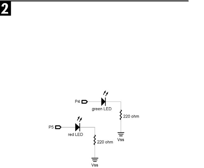
The following program will demonstrate the difficulty in accomplishing this task. Two light-emitting diodes have been added as output indicators on Pin 4 and Pin 5. Wire the LEDs relative to Figure 2.6.
Figure 2.6: Active-High LED Circuit to be Added to the Schematic in Exercise #1
Enter and run the program according to StampPlot Lite procedures. The status of the pushbutton and the LEDs is being indicated. When PB1 is pressed, the LEDs will toggle. Can you be quick enough to make them toggle only once on alternate presses? Try it.
Industrial Control Version 1.1 •Page 37

Experiment #2: Digital Input Signal Conditioning
'Program 2.2 No Debouncing
PAUSE 500
DEBUG "!TITL Toggle Challenge",CR DEBUG "!TMAX 25", CR
DEBUG "!PNTS 300", CR
INPUT 1
INPUT 2
OUTPUT 4
Out4 = 1
OUTPUT 5
Out5 = 0
Loop:
DEBUG IBIN In1, BIN In4, BIN In5, CR
DEBUG DEC 0, CR
IF In1 = 1 THEN Action
GOTO Loop
Action:
TOGGLE 4
TOGGLE 5
GOTO Loop
'Titles the StampPlot screen
'Sets the plot time (seconds)
'Sets the number of data points
'Set P1 as an input
'Set P2 as an input
'Green LED
'Initialize ON
'Red LED
'Initialize OFF
'Plot the digital status.
'Output a 0 to allow for screen shift
'Test the switch
'Optional pause 5 if StampPlot locks up
'Toggle last state
If StampPlot Lite isn’t responding to data sent by the BASIC Stamp, you may need to insert a very short delay in the Loop: routine. A PAUSE 2 or PAUSE 5 (even up to 10 on slower computers) will alleviate any transmission speed problems you may encounter.
It is nearly impossible to press and release the pushbutton fast enough to perform the action only once. The problem is twofold as Figure 2.7 indicates. The program loop executes very fast. If you are slow, the program has a chance to run several times while the switch is closed. Add to this several milliseconds of switch bounce, and you may end up with several toggles during one press.
Page 38 •Industrial Control Version 1.1