

Книги по МРТ КТ на английском языке / Neuro Imaging Redcases
.pdf108 |
RadCases.thieme.com |
RadCases Neuro Imaging |
■ Imaging Findings
A B C
(A) Lateral radiograph of the lumbar spine demonstrates anterior slippage of L5 on S1. There is a gap between the superior (black arrow) and inferior (white arrow) facets of L5. (B) Sagittal T1-weighted image (WI) confirms anterior displacement of L5 with respect to S1, with a fat-filled gap between the superior and inferior facets of L5 (asterisk). (C) Axial T1WI shows elongation of the anteroposterior diameter of the spinal canal secondary to anterolisthesis (arrows).
■ Di erential Diagnosis
•Spondylolysis with spondylolisthesis: This is a focal interruption of the pars interarticularis. This interruption causes forward slippage of the superior vertebral body (spondylolisthesis). If significant anterolisthesis of the vertebral body is present, a fat-filled gap between the pars fragments can sometimes be appreciated.
•Degenerative lumbar spondylolisthesis: Osteoarthritis of the facet joints is characterized by thinning of the cartilage, sclerotic changes in the subchondral bone, osteophyte formation, synovial inflammation, and capsular ligament laxity. In more severe forms of the process, osteoarthritis of a facet joint may lead to hypermobility of the facet joint and then to a spondylolisthesis. Most cases of degenerative spondylolisthesis occur at the L4-L5 level.
•Posttraumatic spondylolisthesis: This is associated with acute fracture of a posterior element (pedicle, lamina, or facets) other than the pars interarticularis.
•Approximately 25% of patients with lumbar spondylolysis eventually have significant lower back pain or sciatica, caused by muscular and ligamentous strain, spinal or foraminal stenosis, facet degeneration, and associated disk degeneration or herniation.
■ Other Imaging Findings
•Radiographs allow visualization and grading of spondylolisthesis but may not always reveal spondylolysis. Dynamic studies in flexion and extension can aid the diagnosis. The “Scotty dog with a broken neck” can be seen on oblique films in patients who have a classic spondylolysis.
•Computed tomography allows better visualization of the spondylolytic defect.
•MRI may visualize edema in the marrow around the site of an acute spondylolytic defect and is helpful for identifying nerve root compression resulting from foraminal or central canal stenosis.
■ Essential Facts
•Spondylolysis is a bone defect in the pars interarticularis.
•It results from repeated microfractures and elongation of a congenitally weakened pars, usually first becoming radiographically visible in late childhood or adolescence.
•Typically, the pars defects remain bridged by fibrocartilage but may form a pseudojoint.
•Occasionally, healing and bone union occur, a phenomenon likely accounting for many of the 10 to 15% of cases with unilateral defects.
•The L5 vertebra is involved in 90 to 95% of patients.
•Men are a ected two to four times more often than women.
¸Pearls & ˚ Pitfalls
¸Bilateral spondylolysis may result in a large degree of
slippage, whereas degenerative facet arthropathy typically results in a lesser degree of displacement.
¸ Degenerative spondylolisthesis is seen most commonly at the L4-L5 level.
˚Sclerosis of the pars and partial volume averaging of adjacent facet arthropathy can produce a focal signal loss in the pars that is nearly indistinguishable from that seen in spondylolysis on MRI.

109
Case 55
A B
C
■ Clinical Presentation
A 32-year-old with neck pain and lower leg numbness after a car accident.
110 RadCases.thieme.com |
RadCases Neuro Imaging |
|
|
■ Imaging Findings |
|
A B 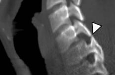 C
C
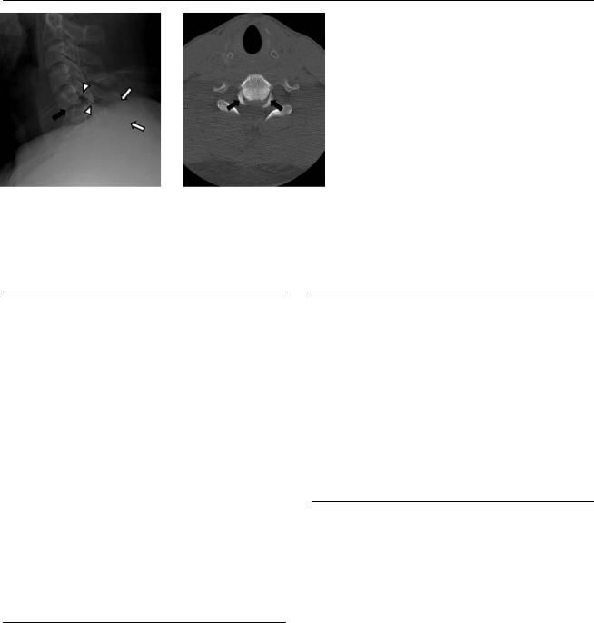
(A) Lateral radiograph of the cervical spine shows “fanning” of the spinous process at the C5-C6 level (white arrows), widening and displacement of the joint facets (arrowheads), wedging of the intervertebral space (black arrow), and fracture of the C5 spinous process. The prevertebral soft tissues are thickened at this level. (B) Axial computed tomography (CT) of the cervical spine at C5-C6 shows posterior displacement of the uncovertebral joints of C6 (arrows).
(C) Reformatted CT maximum-intensity projection image shows the perched facet joint (arrowhead).
■ Di erential Diagnosis
•Anterior subluxation in hyperflexion sprain of the cervical spine: Hyperflexion injuries are associated with localized kyphotic angulation; anterior displacement or rotation; wedge narrowing of the vertebral disk space (widened posteriorly); anterior displacement of the inferior facets, which can appear widened, perched, or completely “locked”; “fanning” of the interspinous space; and anterior pillar fracture.
•Hyperextension injury to the cervical spine: This injury can be associated with fracture of the anterior arch of the atlas, compression fracture of the posterior arch of the atlas, fractures of the dens, traumatic spondylolisthesis of C2 (hangman’s fracture), tear drop fracture, laminar fracture, and wedging of the intervertebral joint space (widened anteriorly).
•Flexion and rotation injury of the cervical spine: This is associated with laminar fractures, unilateral perched facet, rotational subluxation of the vertebral bodies, and misalignment of the spinous processes.
■Essential Facts
•Hyperflexion of the cervical spine causes a disruption of the posterior ligaments.
•There is a disruption of the joint facet capsule with anterior displacement of the inferior joint facets. The inferior articular process of the vertebra above may lie atop (perched) or anterior to (locked) the superior articular process of the vertebra below.
■ Other Imaging Findings
•CT is helpful for the evaluation of fractures and displacements of the facets joints. It also helps to identify fracture fragments.
•Ligamentous injuries are better seen on magnetic resonance imaging (MRI). A T2-weighted fat-saturated sequence is the sequence of choice. MRI is recommended to evaluate the spinal cord; cord edema will show increased signal on the T2-weighted image.
•The uncovered articular surfaces of a displaced zygapophyseal joint have been described as the “naked facet” sign.
¸Pearls & ˚ Pitfalls
¸MRI is helpful to detect soft-tissue and cervical cord
injuries.
¸Rotation in the lateral view of the cervical spine can obscure facet joint displacements.
¸The vertebral arteries run in the transverse foramen of the cervical spine; assessment for vascular injury is nec-
essary.
˚Controversy exists in the literature on how appropriate the term locked facet is because it can suggest stability of a very unstable injury.

111
Case 56
A
■ Clinical Presentation
A 55-year-old man with the sudden onset of right-sided weakness and neck pain.
Further Work-up
B C D
112 |
RadCases.thieme.com |
|
RadCases Neuro Imaging |
|
|
■ Imaging Findings |
|
|
|
A |
B |
C |
|
D |
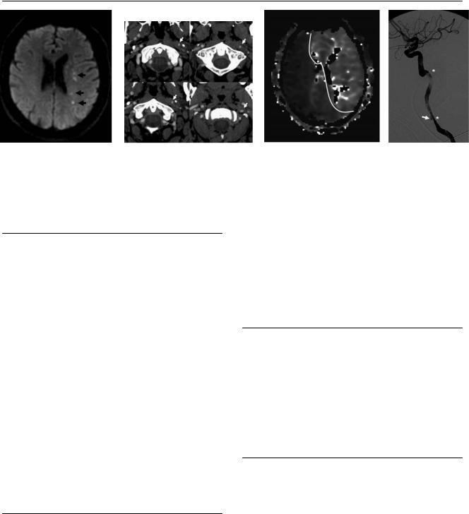
(A) Axial di usion-weighted image (WI) demonstrates multiple punctate foci of restriction in the left centrum semiovale, consistent with acute watershed infarcts (arrows). (B) Serial axial images from a computed tomography (CT) angiogram show narrowing of the left internal carotid artery (ICA) with a rotating flat lumen (arrows). (C) CT perfusion time-to-peak image demonstrates delayed cerebral blood flow in the territory of both anterior cerebral arteries and the left middle cerebral artery (delineated). (D) Digital subtraction angiography shows dissection of the left ICA from its origin, with a long segment of narrowing (between asterisks) and a spiral configuration of the lumen. There is a pseudoaneurysm in the proximal aspect of the dissection (arrow).
■ Di erential Diagnosis
•Carotid dissection: This is characterized by a tear in the intima of the vessel, which allows intraluminal blood to dissect along the layers of the vessel wall, or alternatively a direct hemorrhage from the vasa vasorum of the media into the arterial wall. Luminal narrowing or total occlusion occurs if the hematoma lies just beneath the intima. If the hematoma dissects just beneath the adventitia, a pseudoaneurysm forms. A false lumen occurs if blood reenters the true lumen. The false lumen may remain patent, resolve completely, or thrombose and cause narrowing of the true lumen.
•Traumatic pseudoaneurysm: Traumatic pseudoaneurysm is caused by a disruption in the continuity of the arterial wall. It is a periarterial hematoma contained by adjacent soft tissues. Subsequent encapsulation results in pseudoaneurysm formation. It may be associated with dissection.
•Atherosclerosis: Narrowing in atherosclerosis tends to occur in short segments, at vessel origins, or at sites of turbulent flow. It is usually bilateral. It may be associated with dissection. Ulceration in a plaque may mimic a pseudoaneurysm.
■Essential Facts
•Carotid artery dissection may occur spontaneously or in association with external trauma or vasculopathy (fibromuscular dysplasia and other connective tissue
diseases, such as Ehlers-Danlos syndrome type IV, Marfan syndrome, autosomal-dominant adult polycystic kidney disease, osteogenesis imperfecta type I, and cystic medial necrosis).
•The clinical presentation includes stroke, Horner syndrome, face or neck pain, cranial neuropathy, and pulsatile tinnitus.
•The thrombosed dissection lumen may become the source of distal embolization presenting as a transient ischemic attack or stroke.
•Common locations:
•Cervical ICA 2 to 3 cm distal to the carotid bulb
•Vertebral artery at the level of C1-C2
•Involving multiple vessels
■ Other Imaging Findings
•Angiography: Features include double lumen and intimal flap, arterial stenosis, tapered end, string sign or flame shape, aneurysm formation, and arterial occlusion. Appearance evolves with time.
•Magnetic resonance imaging (MRI): A narrowed eccentric flow void is surrounded by a crescent-shaped area of hyperintensity expanding the vessel diameter. T1 hyperintense signal from mural hematoma.
¸Pearls & ˚ Pitfalls
¸An acute intramural hematoma can be hypointense on
T2WIs and T1WIs and is therefore di cult to delineate from an area of flow void. The intramural hematoma may therefore be missed on MRI within the first 24 to 48 hours after an ICA dissection.
˚MRI may demonstrate T1 hyperintense fat around the vessel, which can mimic an intramural hematoma; fatsuppression techniques are useful in such cases.
˚In-flow phenomena, in the presence of slow blood flow, may mimic intraluminal thrombus. The signal abnormalities are located centrally within the flow void rather than peripherally. Homogeneity of the hyperintense signal on all slices associated with vessel expansion supports dissection rather than slow flow.

113
Case 57
A B
■ Clinical Presentation
A young woman who has fallen from her own height after “the worst headache of her life.”
Further Work-up
C D
114 RadCases.thieme.com |
RadCases Neuro Imaging |
|
|
■ Imaging Findings |
|
A B C D
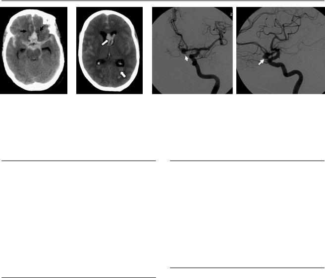
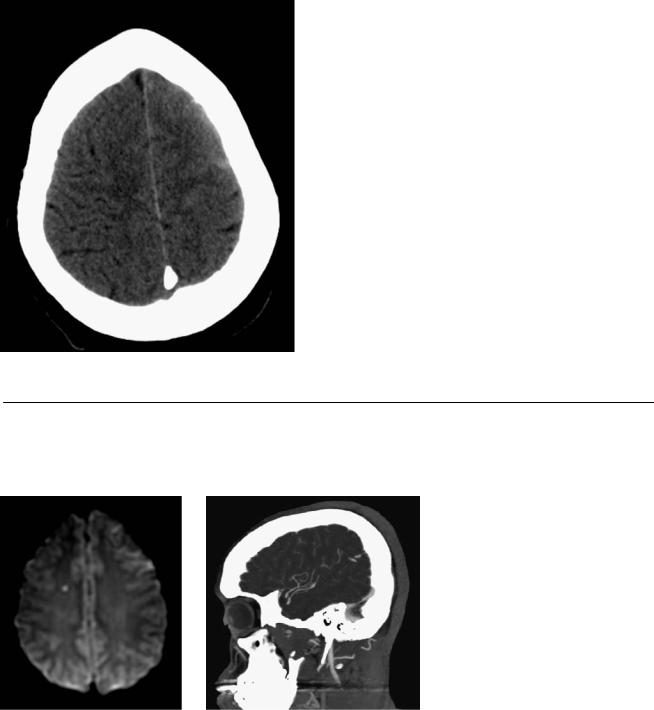
(A)Axial nonenhanced computed tomography (CT) shows subarachnoid hemorrhage (SAH) in the basal cisterns that is more prominent in the interhemispheric region. Areas of low attenuation in the gyri recti are noted, consistent with edema or ischemia (arrows). There is also intraventricular hemorrhage.
(B)Axial nonenhanced CT shows SAH in the interhemispheric and sylvian regions. There is also intraventricular hemorrhage (arrows). (C) Oblique projection of a digital subtraction angiogram (DSA) of the left internal carotid artery (ICA) reveals a lobulated aneurysm in the anterior communicating artery (arrow). There is no narrowing of the vessels to suggest vasospasm. (D) Lateral projection of a DSA of the left ICA shows a lobulated aneurysm in the anterior communicating artery (arrow).
■ Di erential Diagnosis
•Ruptured cerebral aneurysm: This causes SAH that is more extensive in the region of the aneurysm. It may also cause parenchymal or intraventricular hemorrhage.
•Arteriovenous malformation (AVM): This is a less common cause of SAH. Usually, parenchymal hemorrhage predominates. AVM may have calcifications and variable mass e ect.
•Traumatic SAH and frontal lobe contusion: If a trauma patient presents with injuries that are disproportionate to the mechanism of trauma, another cause of subarachnoid and parenchymal hemorrhage should be sought.
■ Essential Facts
•Intracranial aneurysm is a localized pathologic dilatation of cerebral arteries.
•Types: saccular (berry aneurysm), dissecting, fusiform, infectious, traumatic, neoplastic
•Complications:
•Rupture: SAH, parenchymal hematoma, hydrocephalus
•Vasospasm: 4 to 5 days after rupture, secondary infarctions, leading cause of death
•Mass e ect: cranial nerve palsies, headache
•Rebleeding: 50% within 6 months, 50% mortality
•Treatment options: endovascular coiling or craniotomy with clip ligation (clipping)
■ Other Imaging Findings
•CT angiography (CTA) is currently the first-choice examination in cases of SAH as it allows diagnosis of the aneurysm, analysis of its three-dimensional shape, and decisions regarding therapeutic choices.
•DSA is the gold standard and must be performed when the results of CTA and magnetic resonance angiography (MRA) are negative. If a four-vessel angiogram does not demonstrate the aneurysm, the external carotid arteries must be evaluated to exclude a dural fistula.
•MRA can be used to screen for unruptured aneurysms.
¸Pearls & ˚ Pitfalls
¸Aneurysms are multiple in 20% of cases.
¸Useful signs to identify the one that bled:
•Within the SAH
•Largest aneurysm most likely to bleed
•Most irregular aneurysm
•Extravasation of contrast (rare)
•Vasospasm adjacent to bleeding aneurysm
¸There is an increased incidence of aneurysms in au-
tosomal-dominant polycystic kidney disease, aortic coarctation, fibromuscular dysplasia, structural collagen disorders (Marfan syndrome, Ehlers-Danlos syndrome), neurofibromatosis type 1, and α1-antitrypsin deficiency.
˚Do not mistake an infundibular dilatation of the posterior communicating artery for an aneurysm. It is round or conical in shape and 3 mm in maximum diameter. It has no aneurysmal neck, and the posterior communicating artery arises from its apex.

115
Case 58
A  B
B
■ Clinical Presentation
A 19-month-old boy with the diagnosis of neurofibromatosis type 1 undergoing screening magnetic resonance imaging of the brain.
Further Work-up
C 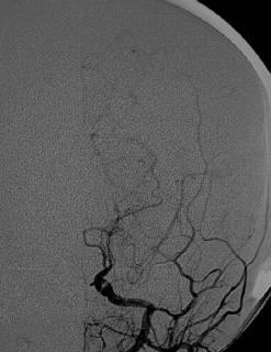 D
D

116 RadCases.thieme.com |
RadCases Neuro Imaging |
|
|
■ Imaging Findings |
|
A B C D
(A) Axial T2-weighted image (WI) of the brain shows narrowing of the left internal carotid artery (ICA) in the supraclinoid segment (arrow). (B) Magnetic resonance angiography (MRA) of the brain reveals narrowing of the left ICA with an absent flow-related signal in the left middle cerebral artery (MCA; arrow). There is also a paucity of branches of the right MCA. (C) Digital subtraction angiogram (DSA) of the left common carotid artery shows tapering and occlusion of the distal ICA. Prominent leptomeningeal collateral vessels are noted (arrow). (D) DSA of the left common carotid artery shows attenuation of the right MCA and both anterior cerebral arteries (ACAs). Hypertrophic leptomeningeal vessels give the appearance of a “pu of smoke” (arrow).
■ Di erential Diagnosis
•Moyamoya disease: Moyamoya disease is characterized by occlusive changes in the distal ICAs or proximal ACAs or MCAs. Hypertrophy of the leptomeningeal collaterals results in a “pu of smoke” appearance on the angiogram.
•Embolism of cardiac origin: This causes occlusion of large or medium-size vessels with acute infarcts. It does not result in proliferation of the leptomeningeal vessels.
•Fibromuscular dysplasia (FMD): FMD causes multifocal concentric luminal narrowing alternating with areas of mural dilatation that are wider than the original lumen (“string of beads”). It may be associated with arterial dissection, intracranial aneurysms, and arteriovenous fistulas.
■Essential Facts
•Moyamoya disease causes progressive occlusion of branches of the circle of Willis.
•The collateral network results in a “pu of smoke” appearance on angiograms.
•Moyamoya disease a ects children in the first decade of life or adults in the third or fourth decade.
•Associated conditions are sickle cell anemia, Down syndrome, Fanconi anemia, and neurofibromatosis type 1. Moyamoya disease may also be associated with radiation therapy of the brain and may occur in families.
■ Other Imaging Findings
•MRA can delineate the occlusive changes and collateral networks.
•MR perfusion provides information regarding the cerebrovascular reserve that may aid in management.
•Cerebral angiography:
•Stenosis or occlusion at the terminal portion of the ICA or the proximal portion of the ACAs or MCAs
•Abnormal vascular networks in the vicinity of the occlusive or stenotic areas
¸Pearls & ˚ Pitfalls
¸The term moyamoya disease should be reserved for those
cases in which the characteristic angiographic pattern is idiopathic.
¸ The term moyamoya syndrome is used when the underlying condition is known.
˚Inadequate visualization of the flow void of the proximal vessels of the circle of Willis on axial T2WIs of the brain should raise the suspicion of occlusive changes.
117
Case 59
A
■ Clinical Presentation
A 24-year-old postpartum patient with a history of headache.
Further Work-up
B C  D
D