

3troubleshootingjunos
.pdfTroubleshooting JUNOS Platforms
|
|
|
Reproduction |
|
|
|
|
|
|
||
|
|
Craft Int rface—No LCD Dis lay Example |
|||
|
|
The slide illustrat s a typical view of the SRX5800 Craft Interface. Although the Craft |
|||
|
|
Interface do s not have the LCD display, system component LEDs provide enough |
|||
|
|
information to identify their status. |
|||
Not |
for |
|
|
|
|
|
|
|
|
||
Overview of JUNOS Platforms • Chapter 2–57
Troubleshooting JUNOS Platforms
|
|
|
C aftReproductionInterface indicate the status of the Routing Engines or Host |
|
|
|
|
|
|
||
|
|
System Status LEDs |
|||
|
|
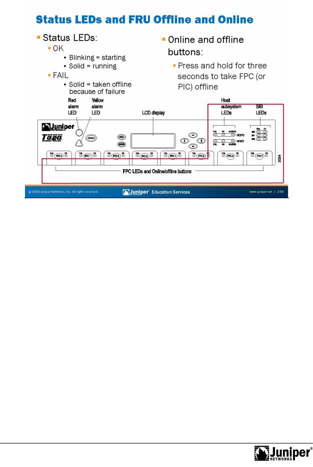
The system status LEDs include the following: |
|||
|
|
• |
FPC LEDs: Two LEDs exist—one green for OK and one red for fail. These |
||
|
|
|
lights indicate the status of each FPC. Each LED pair the Craft |
||
|
for |
||||
|
|
|
Inte face aligns with the corresponding FPC module slot. |
||
|
|
• |
Routing Engine or Host LEDs: A red fail LED and a green OK LED on the |
||
|
|
|
modules. |
||
Not |
FPC and PIC Offline Buttons |
||||
|
|
|
|
||
FPC (or PIC) offline buttons allow you to take an FPC (or PIC) offline gracefully. Press and hold the offline button near the FPC (or PIC) until the green OK LED extinguishes. For systems with fixed FPCs, like the M7i and M10i, the online and offline buttons help prepare a PIC for removal from the system.
Chapter 2–58 • Overview of JUNOS Platforms
Not
Troubleshooting JUNOS Platforms
|
Reproduction |
|
|
||
|
|
||||
Red Alarm |
|
|
|
||
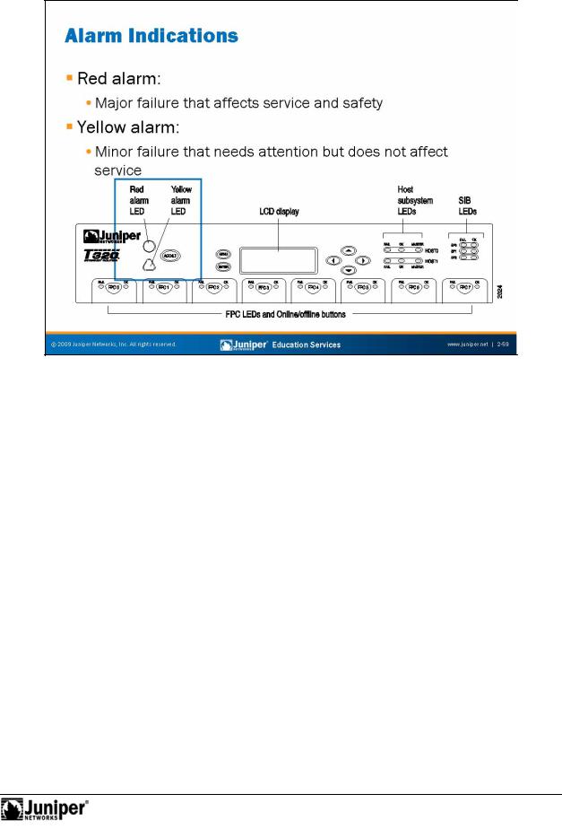
The red alarm LED indicat s a system failure likely to cause an interruption in service. |
|||||
Examples of |
d alarms include the following: |
||||
for |
• |
outing Engine failure; |
|||
• |
Cooling system failure; and |
||||
|
|||||
|
• |
Interface loss of light or framing. |
|||
Yell w Alarm
The yellow alarm LED indicates a system warning not likely to interrupt service, but if left uncorrected, might eventually cause a service interruption. Examples of yellow alarms include the following:
•Maintenance alert;
•FPC with recoverable errors; and
•Cooling system problems.
You can configure the mapping of various events to alarm actions of ignore, yellow, or red. Environmental and safety-related alarms are not mappable.
Overview of JUNOS Platforms • Chapter 2–59
Troubleshooting JUNOS Platforms
Not
LCD Display
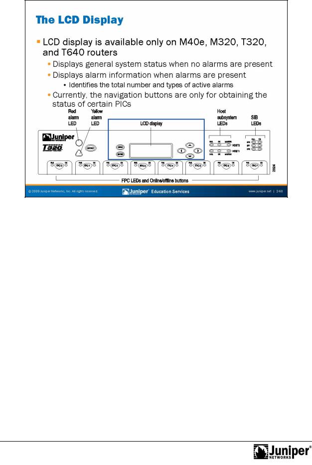
The Craft Interface s l |
platforms supports a four-line LCD screen with six |
|
navigation buttons. The LCD scr |
n operates in one of two display modes. The default |
|
or idle mode, displays the current system status until alarm mode preempts it. The |
||
following list contains the basic status information in the LCD display: |
||
• |
Router’s name on the first line; |
|
• |
NumberReproof days, hours, minutes,ductionand seconds that the system has been |
|
|
running on the second line; and |
|
• |
Status messages on the fourth line, which are various system status |
|
|
messages that cycle at 3-second intervals. |
|
forYou can alter the idle mode display by specifying a message of your choosing with the set chassis display message operational mode command. The Craft Interface display cycles between the user-defined and standard display every
2 seconds unless you also configure the permanent argument. The user-defined message only persists for 5 minutes, however. You can view the LCD display, along with an ASCII representation of the status LEDs, with a show chassis craft-interface operational mode command.
Chapter 2–60 • Overview of JUNOS Platforms

Troubleshooting JUNOS Platforms
|
|
|
Reproduction |
|
|
|
|
|
|
||
|
|
Interface Ov rvi w |
|||
|
|
The slide highlights the topic we discuss next. |
|||
Not |
for |
|
|
|
|
|
|
|
|
||
Overview of JUNOS Platforms • Chapter 2–61
Troubleshooting JUNOS Platforms
Permanent InterfacReproductions
Each JUNOS platform has s v ral rmanent interfaces. One, the management Ethernet interface, provid s an out-of-band method for connecting to the device. You can connect to the management interface over a network using utilities such as SSH and Telnet, and SNMP can also use the management interface to gather statistics from the outer. The out-of-band management interface requires configuration to ope ate. The names of out-of-band management interfaces vary depending on the platf m. F example, most JUNOS platforms use fpx0 for out-of-band management, while the EX Series uses me0.
for Not
A sec nd permanent interface provides internal Ethernet-based connectivity between
he RE and the PFE. This interface is named fxp1 on most platforms. In the case of the M320, the interface operates at 1 Gbps and is named bcm0. A proprietary protocol known as the Trivial Network Protocol (TNP) operates over these interfaces. Note that raffic arriving on the out-of-band interface cannot egress on a PFE port, and vice versa. This design isolates the out-of-band network from transient traffic and preserves bandwidth on the internal fxp1 or bcm0 control interface.
Platforms with redundant REs use a third interface (fxp2 or em0) to interconnect the
REs for heart-beat and internal communications exchanges.
Internal interfaces like fxp1 and fxp2 do not require any configuration. You should not attempt to configure or modify these interfaces.
Chapter 2–62 • Overview of JUNOS Platforms

Not
Troubleshooting JUNOS Platforms
TransientReproductionInt rfac s
Each FPC can support from two to four PICs, depending on the platform. PICs provide the actual physical int rfac s to the network. These physical interfaces are the device’s transient interfaces. We refer to them as transient because you can hot-swap
FPCs and PICs most platforms at any time. From the point of view of the PFE, you forcan place any FPC into any slot, and you can generally place any combination of PICs
in any location on an FPC. These characteristics makes PFE interfaces transient.
Y u can use a transient interface for networking or to provide hardware-assisted services within the device. Service examples include IPsec, stateful firewall, and GRE tunneling. You must configure each of the transient interfaces based on the slot in which you installed the FPC, the location in the FPC in which you installed the PIC, and the port to which you connect.
Continued on next page.
Overview of JUNOS Platforms • Chapter 2–63

Troubleshooting JUNOS Platforms
Transient Interface Naming
JUNOS Software uses a standard naming convention when naming interfaces. You must configure each of the standard interfaces based on the slot in which you install the FPC, the location of the PIC, and for some PICs, the port to which you connect. When dealing with a channelized PIC you must also reference the correct channel and time slot value using a :n form of syntax.
Interface Naming Example
|
The slide shows an example of a channelize interface name that makes use f the |
|
|
colon (:) delimiter to identify a time slot within the channel bundle. |
|
|
for |
Reproduction |
Not |
|
|
|
|
|
Chapter 2–64 • Overview of JUNOS Platforms
Troubleshooting JUNOS Platforms
|
|
Reproduction |
|
|
||
|
|
|
||||
|
|
Logical Int rfac |
s |
|||
|
|
Each physical int rface d scriptor can contain one or more logical interface |
||||
|
|
descriptors. Th se |
scriptors allow you to map one or more logical (sometimes |
|||
|
|
referred to as virtual) interfaces to a single physical device. Creating multiple logical |
||||
|
for |
|
|
|
||
|
|
inte faces is useful for ATM and Frame Relay networks, where you can associate |
||||
|
|
multiple virtual circuits or Data Link Layer connections with a single physical interface. |
||||
|
|
Ci cuit Identifier Versus Unit Number |
||||
|
|
The unit number and the circuit identifier are different in meaning. The circuit |
||||
Not |
identifier identifies the logical tunnel or circuit, while the unit identifies a logical |
|||||
partition of the physical interface. |
||||||
|
|
|||||
Although not required, we generally consider it best practice to keep the unit number and circuit identifier identical. This practice can greatly aid in troubleshooting when you have many logical circuits.
Point-to-Point Encapsulations
PPP and Cisco HDLC encapsulations support only a single logical interface, and its logical unit number must be zero. Frame Relay and ATM encapsulations support multiple logical interfaces, so you can configure one or more logical unit numbers.
Continued on next page.
Overview of JUNOS Platforms • Chapter 2–65

Troubleshooting JUNOS Platforms
Addressing Issues
A JUNOS platform can have more than one address on a single logical interface. Issuing a second set command does not overwrite the previous address but simply adds to that address. Use of the CLI’s rename command is an excellent way to correct addressing mistakes.
|
for |
Reproduction |
Not |
|
|
|
|
Chapter 2–66 • Overview of JUNOS Platforms