

3troubleshootingjunos
.pdfTroubleshooting JUNOS Platforms
|
|
Reproduction |
|
|
|
|
|
|
|||
|
|
I-Chip Ov rvi w |
|
|
|
|
|
Inheriting all the f atur |
s of the LMNR chips, the I-chip is the Juniper Networks |
||
|
|
next-generation Int rn |
processor delivering PFE on a chip. Each I-chip can send |
||
|
|
20 Gbps of bandwidth to the fabric and can receive 17 Gbps of bandwidth from the |
|||
|
for |
|
|
|
|
|
|
fab ic. The I-chip’s flexibility comes through programmability, a rich instruction set, |
|||
|
|
and silicon development. Various Juniper Networks platforms deploy the I-chip, |
|||
|
|
including the M120, the MX Series, and the SRX Series. |
|||
|
|
New Capabilities |
|
|
|
Not |
The I-chip provides industry-leading scalability, allowing significant headroom in |
||||
multiple dimensions, including VLANs, logical interfaces, routes, counters, number and size of firewall filters, and policing and shaping technologies. It provides complete control of any traffic management attributes of a packet, allowing manipulation of QoS attributes in a very sophisticated fashion. Layer 2 and Layer 3 classification can mix on the same physical port. This flexibility provides intelligent end to end QoS, because network elements in other segments might use different markings to determine classification. The data structures used in the I-chip allow it to scale multicast traffic at port speed without compromising performance.
Overview of JUNOS Platforms • Chapter 2–47
Troubleshooting JUNOS Platforms
|
|
|
Reproduction |
|
|
|
|
|
|
|
|||
|
|
Deterministic Performance |
||||
|
|
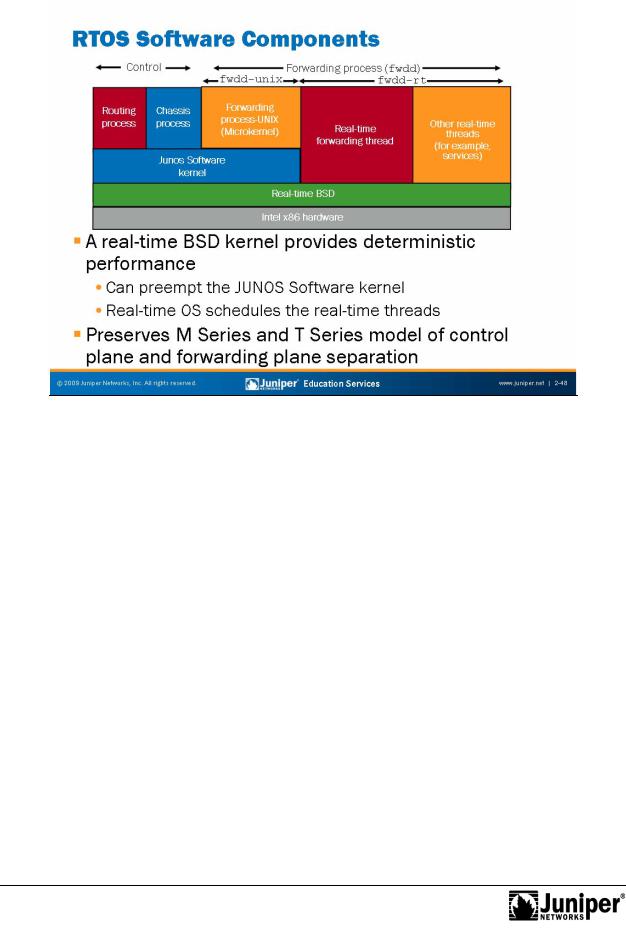
The J Series Routing Engine and software PFE both implement on the primary x86 |
||||
|
|
architecture microproc ssor. A al-time operating system kernel mediates access to |
||||
|
|
the underlying hardware. The real-time kernel ensures that operating system services |
||||
|
forwarding |
|||||
|
|
delive y occu s in a constant, load-independent, amount of time. This process ensures |
||||
|
|
that the fo wa ding and services real-time threads deliver predictable packet |
||||
|
|
forwa ding pe fo mance. |
||||
|
|
C ntr l and Forwarding Separation |
||||
Not |
Separate real-time processes maintain logical separation between the control plane |
|||||
and |
plane. Control plane processes continue to run on the traditional |
|||||
|
|
|||||
JUNOS Software kernel that is a client of the real-time kernel. Forwarding and services hreads run directly on the real-time kernel.
Chapter 2–48 • Overview of JUNOS Platforms
Not
Troubleshooting JUNOS Platforms
|
Reproduction |
|
|
|
|
|
|||
J Series Virtual Pack |
t Forwarding Engine |
|||
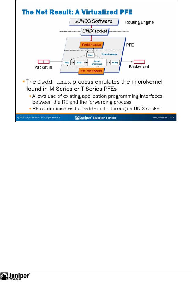
The J Series software PFE maintains many of the benefits of the microkernel and |
||||
ASIC-based PFE found |
M Series and T Series platforms at a fraction of the cost. A |
|||
UNIX socket provides the internal link between the RE and PFE and allows reuse of the |
||||
for |
|
|
|
|
JUNOS Software control plane from the M Series and T Series platforms on the J Se ies platform.
Overview of JUNOS Platforms • Chapter 2–49
Troubleshooting JUNOS Platforms
General FPC CharactReproductionristics and Features
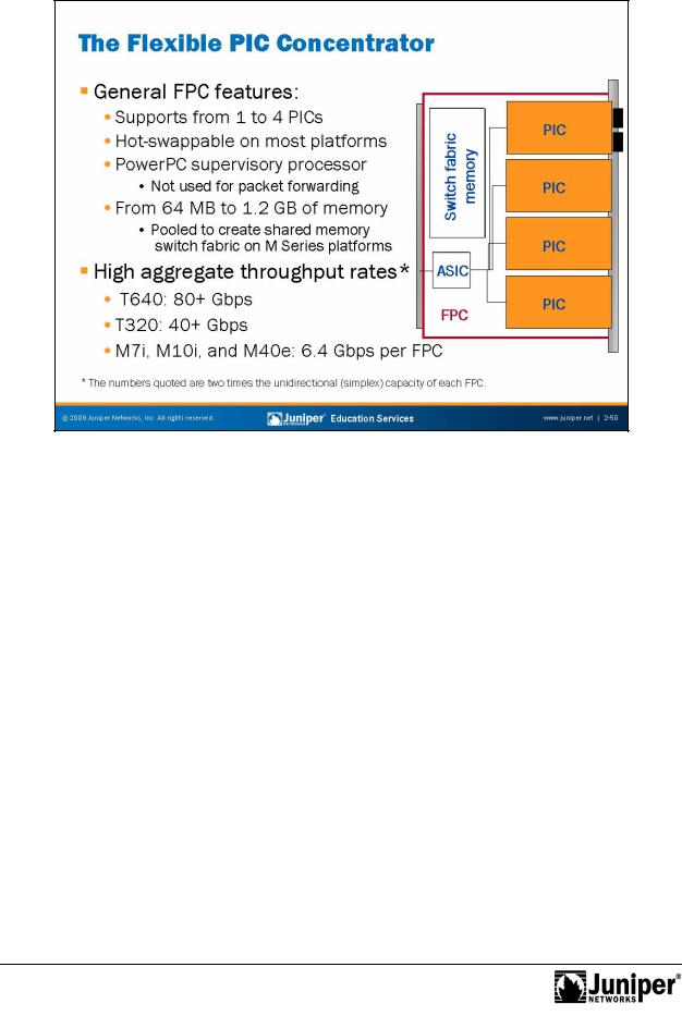
FPCs install into the backplane from the front of the chassis. You can install an FPC into any FPC slot; it do s not quire any specific order. If an FPC does not occupy a slot, you must install a blank FPC carrier to shield the empty slot so that cooling air can ci culate p operly through the card cage. FPCs can support from one to four PICs, depending upon specifics. For example, an OC192 interface on an M120 router goes into a Type 3 FPC, which has only one slot—such a high-speed interface consumes all available FPC bandwidth. Most FPCs support four PIC connectors; current exceptions are the T320 and the M320, which support two PIC connectors per Type 3 FPC, the M120 as mentioned, and the M40e Type 2 FPCs, which also support only a single PIC.
|
When you install an FPC into a running system, the FPC requests its operating |
forsoftware from the Routing Engine, runs its diagnostics, and enables its PICs on the |
|
Not |
FPC slot. FPCs are hot-swappable on all platforms except the M7i and the M10i |
because these routers have FPCs that combine with the system board components to |
|
create a CFEB. The CFEB on the M7i and the M10i is hot-insertable but not |
|
hot-removable. |
|
Note that when you remove or install an FPC on an M Series router, the system must |
|
re-partition the shared memory pool; this process results in about 200 milliseconds of |
|
disruption to all packets associated with the affected PFE. T Series platforms contain |
|
from one to two complete PFEs on each FPC, and therefore removal or insertion of |
|
FPCs does not affect packet forwarding on other FPCs. |
|
Continued on next page.
Chapter 2–50 • Overview of JUNOS Platforms

Troubleshooting JUNOS Platforms
General FPC Characteristics and Features (contd.)
A portion of the memory associated with each FPC pools together with the memory from other FPCs to create the M Series shared memory switch fabric. The actual amount of FPC memory varies by FPC type, but in all cases at least 100 milliseconds of delay buffer exists (for each transmit and receive, yielding a total of
200 milliseconds of delay buffering). Currently, the amount of memory present on a
Industry-Leading Throughput
given FPC ranges from 256 MB on the M7i FPC to 1.2 GB on the T640 FPC3. In the latter case,Reproductionthis memory yields approximately 600 MB per PFE complex.
ABC chipset-based routers have an aggregate slot throughput |
f 6.4 Gbps. LMNR |
|
chipset-based platforms increase aggregate slot throughput |
|
a respectable 20 Gbps |
for the M120, 40 Gbps for the M320 an the T320, and 80 |
Gbps for the T640. |
|
Not |
for |
|
Overview of JUNOS Platforms • Chapter 2–51
Troubleshooting JUNOS Platforms
|
|
Reproduction |
|
|
|
|
|
|
|||
|
|
MX Series Dense Port Conc ntrators |
|||
|
|
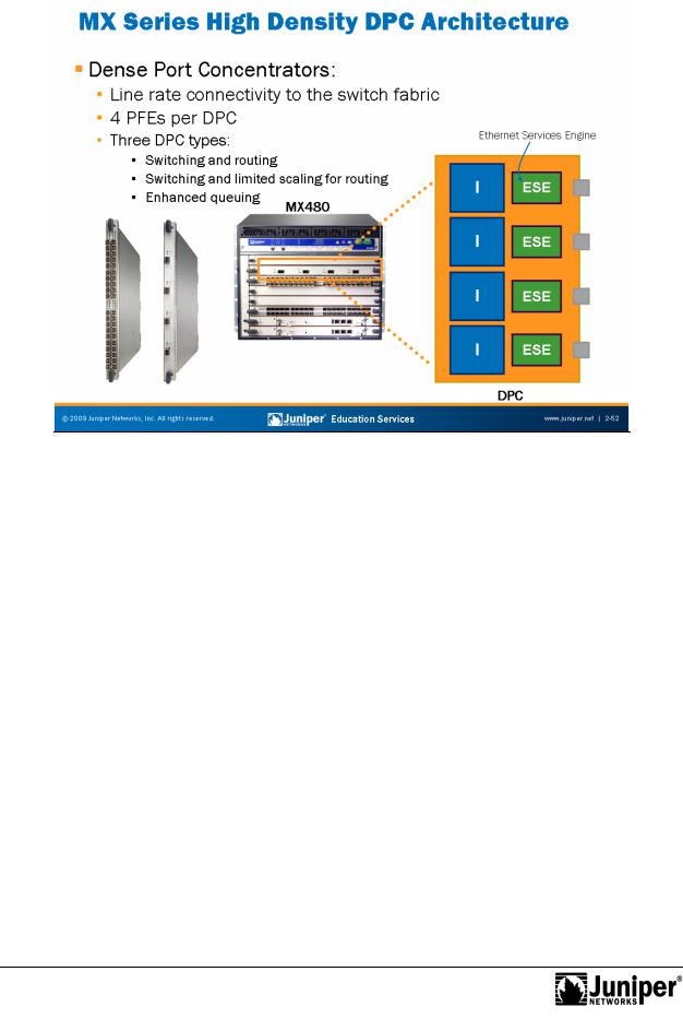
All DPCs come in eith a small form-factor pluggable transceiver (SFP) or a 10-gigabit |
|||
|
|
small form-factor pluggable transc iver (XFP), which uses the most optimal port |
|||
|
|
density with cost efficiency. Each DPC has connections to the switch fabric providing |
|||
|
for |
||||
|
|
lineate connectivity for each port on the card. |
|||
|
|
DPCs p ovide multiple physical interfaces and PFEs on a single board that installs in a |
|||
|
|
sl t in the MX Se ies router. A DPC receives incoming packets from the network and |
|||
|
|
sends utg ing packets to the network. Each DPC contains four PFEs. The PFEs on a |
|||
|
|
DPC have purpose-built ASICs that perform packet processing and forwarding. Each |
|||
|
|
PFE c nsists one I-chip for Layer 3 processing and one Layer 2 network processor. |
|||
Not |
Multiple PFEs contribute to the system’s full packet forwarding redundancy and |
||||
resiliency. |
|||||
|
|
||||
The three types of DPCs are switching and routing (DPCE-R), switching and limited scaling for Layer 3 (DPCE-X), and enhanced queuing (DPCE-Q). The DPCs support a wide range of Layer 2 and Layer 3 Ethernet functionality, including 802.1Q VLAN, link aggregation, circuit cross-connect, Virtual Router Redundancy Protocol (VRRP), Layer 2 to Layer 3 mapping, and port monitoring. Additionally, the DPCs support filtering, sampling, load balancing, rate limiting, class of service, and other key features necessary for deployment of dependable, high-performance Ethernet services.
Chapter 2–52 • Overview of JUNOS Platforms
Troubleshooting JUNOS Platforms
|
|
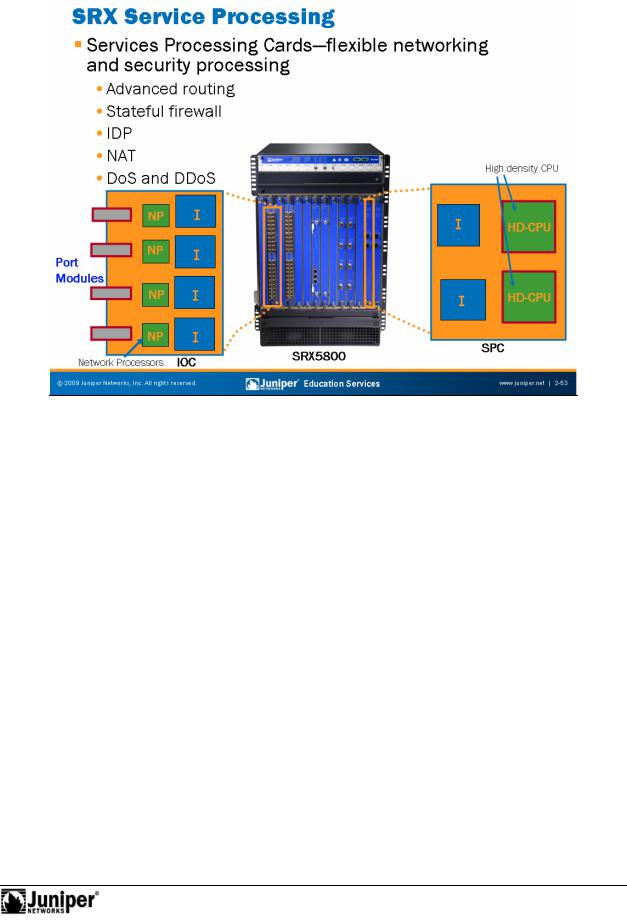
SPCs andReproductionREs are separate—both physically and logically. This separation of |
|
|
|
the |
|||
|
|
Service Proc |
ssing Cards |
|
|
|
SPCs are blad |
s that provide the capacity to perform the heavy lifting of processing |
|
|
|
network pack ts. The chassis must have at least one SPC to operate. You realize the |
||
|
|
true elegance of this design when your system has more than one SPC installed. |
||
|
|
for |
|
|
|
|
Rather than the chassis having two or more “brains”, as in traditional network |
||
|
|
a chitecture, the addition of a new SPC essentially results in a larger system that can |
||
|
|
pe m many more tasks at a given time. To ensure the highest level of reliability, the |
||
|
|
c ntr l and data planes ensures that a fault on any of the SPCs does not result in |
||
|
|
catastrophic failure of the entire chassis. You can see the importance of this concept |
||
|
|
in a security situation such as a denial of service (DoS) attack. When the attack |
||
Not |
|
|
||
launches, your efforts to contact the system do not simply become part of network traffic. Because the control plane remains separate from traffic flow, you can immediately respond to network-threatening situations to divert the attack, while all the SPCs continue to process network traffic.
Overview of JUNOS Platforms • Chapter 2–53
Troubleshooting JUNOS Platforms
|
|
n a given PIC vaReproductionies with the PIC and platform type. For example, M40e PICs |
|
are |
|
|
|
||
|
|
PIC Overview |
||
|
|
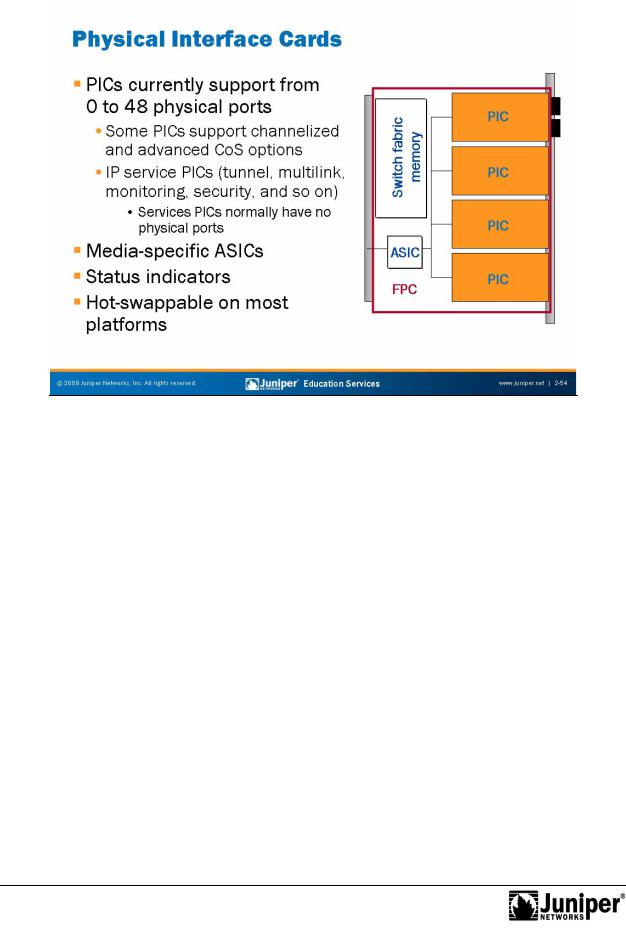
PICs provide the physical conn ction to various network media types. PICs receive |
||
|
|
incoming packets from the twork and transmit outgoing packets to the network. |
||
|
|
During this process, each PIC performs appropriate framing and signaling for its |
||
|
|
media type. Befo e transmitting outgoing data packets, the PIC adds media-specific |
||
|
|
framing to the packets received from the FPCs. You can install up to four PICs into |
||
|
|
slots on each FPC. PIC types can intermix within the same FPC. The number of ports |
||
|
|
available with as many as 48 Fast Ethernet ports. |
||
|
|
IP services PICs enable a hardware assist for complex packet processing functions. |
||
Not |
Examples include the tunnel services and multilink services PICs. With the tunnel |
|||
|
forservices PIC, routers can function as the ingress or egress point of an IP over IP |
|||
unicast tunnel, a generic routing encapsulation (GRE) tunnel, or a Protocol Independent Multicast sparse mode (PIM-SM) tunnel. The multilink PIC uses the Multilink Point-to-Point Protocol (MLPPP) and Multilink Frame Relay (MLFR, FRF 1.5) to group up to eight T1 or E1 links per bundle, yielding a service offering ranging from 1.5 Mbps through 12 Mbps (T1) or 2 Mbps through 16 Mbps (E1).
Continued on next page.
Chapter 2–54 • Overview of JUNOS Platforms

Troubleshooting JUNOS Platforms
Media-Specific ASIC
Each PIC has an ASIC that performs control functions tailored to the PIC’s media type. For instance, an ATM PIC and a Fast Ethernet PIC each contain unique ASICs—or field-programmable gate arrays (FPGAs)—that are specifically suited to the particulars of each medium.
PIC StatusReproduction
Each PIC supports one or more status LEDs that accommodate quick verification of the PIC, and in some cases, the port’s operational status.
Hot-Pluggable in Most Platforms
You can replace or install PICs without removing the asso ia ed FPC on most platforms.
Note that you should always take care to take a PIC offline before removing it from its FPC to minimize system disruption. You sho ld expect small amounts of packet loss on all PICs sharing the affected FPC when hot-swapping PICs on M Series platforms
(excludes the M320, which is based |
a T Series PFE). This momentary disruption is |
the result of the FPC underg ing a l gical reset in reaction to the insertion and |
|
removal of a PIC. Failing to take a PIC |
fflin before removing it from its FPC can result |
in damage to the system or a PFE eset.
Not |
for |
|
Overview of JUNOS Platforms • Chapter 2–55
Troubleshooting JUNOS Platforms
Not
|
Reproduction |
|
|
|
|
|
|||
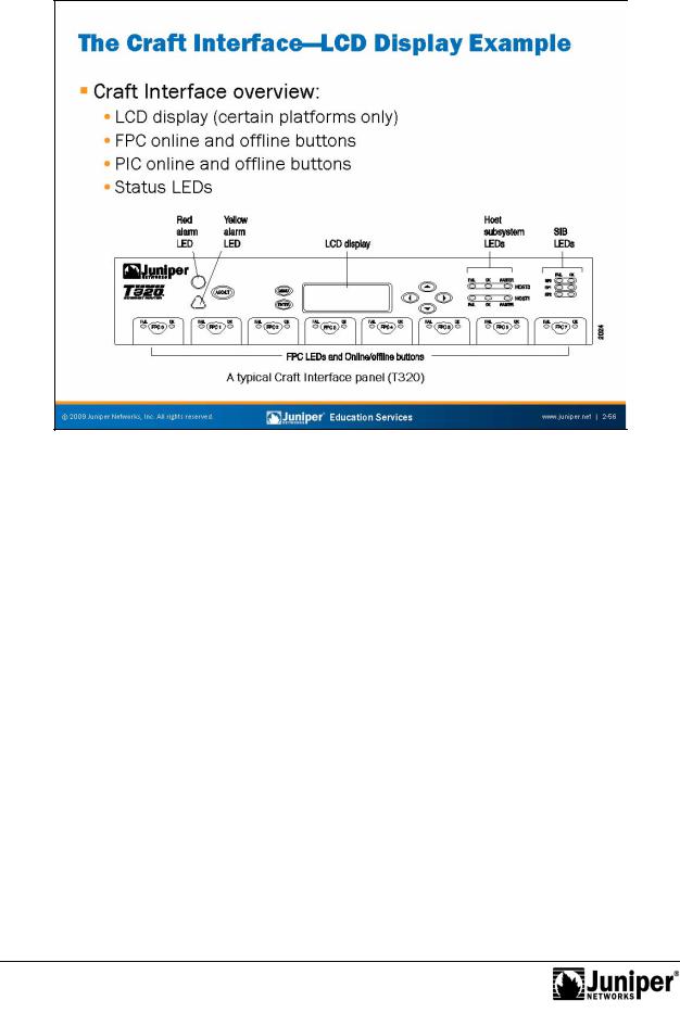
Craft Interface |
|
|
|
|
The Craft Interface is the coll ction of mechanisms on some JUNOS platforms that |
||||
allows you to view syst |
m status m ssages and troubleshoot the router. The Craft |
|||
Interface is located |
the front of the chassis and typically consists of various system |
|||
for |
|
|
|
|
status LEDs and FPC (or PIC) online and offline buttons. On supported platforms the Craft Inte face includes an LCD screen that provides status reporting for the entire system.
The M7i’s FIC and the M10i’s HCM card provide PIC offline and online functionality.
Chapter 2–56 • Overview of JUNOS Platforms