

3troubleshootingjunos
.pdfNot
Troubleshooting JUNOS Platforms
Reproduction |
|
|
|
|
|||
Displaying Int |
rface Status at a Glance |
||
Use the show int rfac s terse command to display a terse listing of all |
|||
interfaces install |
in the d vice along with their administrative and Data Link Layer |
||
status. The table on the slide explains the meaning of the Admin and Link status indications.
forWhen an interface is administratively disabled, the physical interface has an Admin status of down and a Link status of up, and the logical interface has an Admin status of up and a Link status of down. The physical interface has a Link status of up because the physical link is healthy (no alarms). The logical interface has a Link status of down because the Data Link Layer cannot establish end to end.
When an interface is not administratively disabled and the Data Link Layer between the local device and the remote device is not functioning, the physical interface has an Admin status of up and a Link status of up while the logical interface has an Admin status of up and a Link status of down. The physical interface has a Link status of up because the physical link is healthy (no alarms). The logical interface has a Link status of down because the Data Link Layer cannot establish end to end.
If the Data Link Layer between the local device and the remote device is up and running, both the physical and logical interfaces have an Admin status of up and a Link status of up, as shown in the case of the so-0/1/2 interface on the slide.
Interface Troubleshooting • Chapter 5–11
Troubleshooting JUNOS Platforms
|
|
Reproduction |
|
|
|
|
|
||
|
|
Standard Interface Status |
||
|
|
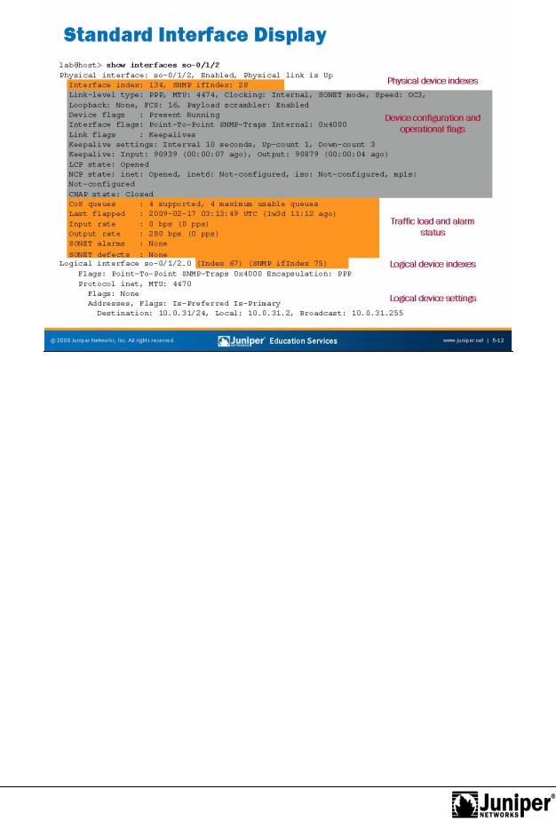
Use the show int rfac s command without the terse or detailed switches to |
||
|
|
display standard information about the named interface (or all interfaces when you do |
||
|
|
not identify a specific interface). The slide provides sample output for an OC-3C |
||
|
|
SONET inte face. The callouts the slide help illustrate how interfaces partition into |
||
|
|
physical devices and logical units in JUNOS Software. |
||
|
|
Each physical and logical interface is referenced by two index numbers within JUNOS |
||
|
|
S twa e. An inte face index is assigned to each interface at boot time depending |
||
|
|
up n the rder in which that interface activates. The SNMP ifIndex is used to |
||
|
|
identi y and reference that interface when performing SNMP MIB walks. Note that the |
||
Not |
indexes assigned to the physical interface device (ifd) differ from the index used to |
|||
|
foridentify the logical device (ifl). Wherever possible, the SNMP ifIndex values are |
|||
persistent across reboots or in the event of hardware additions and deletions that result from PIC or Flexible PIC Concentrator (FPC) insertion and removal.
The output of a show interfaces command also includes a section on the device-level configuration and its operational flags.
Continued on next page.
Chapter 5–12 • Interface Troubleshooting

Not
Troubleshooting JUNOS Platforms
Standard Interface Status (contd.)
The output of a show interfaces command displays the device-level configuration and provides additional information about the device operation through various flags. These flags include the following:
|
• |
Down: Device was administratively disabled; |
|
|
• |
Hear-Own-Xmit: Device hears its own transmissions; |
|
|
•ReproductionLink-Layer-Down: Interface keepalives indicate that the link is |
||
|
• |
Link-Layer-Down: The link-layer protocol failed to successfully |
|
|
|
connect with the remote endpoint; |
|
|
• |
Loopback: Device is in physical loopback; |
|
|
• |
Loop-Detected: The Data Link Layer rece ved frames that it sent and |
|
|
|
suspects a physical loopback; |
|
|
• |
No-Carrier: Where the media supports arrier re ognition, this flag |
|
|
|
indicates that no carrier is currently visible; |
|
|
• |
No-Multicast: Device does not s |
pport m lti ast traffic; |
|
• |
Present: Device is physically present and recognized; |
|
|
• |
Promiscuous: Device is in promiscuous mode and sees frames |
|
|
|
addressed to all physical a resses |
the medium; |
|
• |
Quench: Device is satiated because it overran its output buffer; |
|
|
• |
Recv-All-Multicasts: No multicast filtering (promiscuous); and |
|
|
• |
Running: Device is active and enabled. |
|
One or more flags h lp communicate the status of the interface. These flags include |
|||
the following: |
|
||
|
• |
Admin-T st: Interface is in test mode, which means that some sanity |
|
|
|
checking, such as loop detection, is disabled; |
|
for |
• |
Disabled: Interface is administratively disabled; |
|
• |
Hardware-Down: Interface is nonfunctional or incorrectly connected; |
||
|
incomplete; |
|
|
• |
No-Multicast: Interface does not support multicast traffic; |
||
• |
Point-To-Point: Interface is point to point; |
||
• |
Promiscuous: Interface is in promiscuous mode and sees frames |
||
|
addressed to all physical addresses; |
|
|
|
• |
Recv-All-Multicasts: No multicast filtering (promiscuous); |
|
|
• |
SNMP-Traps: SNMP traps are enabled; and |
|
|
• |
Up: Interface is enabled and operational. |
|
Continued on next page.
Interface Troubleshooting • Chapter 5–13

Troubleshooting JUNOS Platforms
Standard Interface Status (contd.)
Flags also indicate the operational status of the device link layer protocol. These flags include the following:
• |
Give-Up: Link protocol does not continue to attempt to connect after |
|
repeated failures; |
• |
Reproduction |
Keepalives: Link protocol keepalives are enabled; |
|
• |
Loose-LCP: PPP does not use Link Control Protocol (LCP) to i dicate |
|
whether the link protocol is up; |
• |
Loose-LMI: Frame Relay will not use Local Management Interface (LMI) |
|
to indicate whether the link protocol is up; |
• |
Loose-NCP: PPP does not use Network Control Pro ocol (NCP) |
|
indicate whether the device is up; and |
• |
No-Keepalives: Link protocol keepalives are disabled. |
The output also summarizes th device-level traffic load, whi h displays in both bits and packets per second, as well as any alarms that might be active. The final portion of the command output displays the configuration and stat s of each logical unit defined on that device. In this example, a single unit is present with support for the inet protocol family.
Not |
for |
|
Chapter 5–14 • Interface Troubleshooting
Troubleshooting JUNOS Platforms
|
|
Reproduction |
|
|
|
|
|
|
|||
|
|
Displaying Input and Out ut Errors for the Interface |
|||
|
|
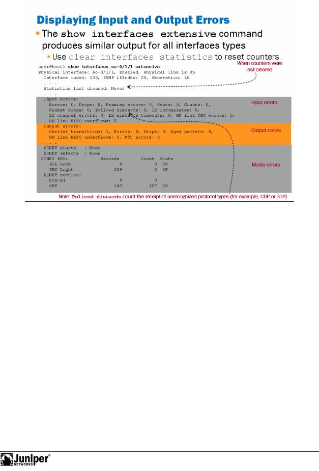
Use the show int rfac s extensive command to display input errors |
|||
|
|
(extensive output only) the interface. Use the clear interfaces |
|||
|
|
statistics interface-name command to reset the counters for the specified |
|||
|
for |
|
|
|
|
|
|
inte face; omit an interface name to clear all interface statistics. The following list |
|||
|
|
explains some of the less obvious counters: |
|||
|
|
• |
Errors: Displays the sum of the incoming frame aborts and FCS errors. |
||
|
|
• |
Policed discards: Displays the frames that the incoming packet |
||
|
|
|
match code discarded because they were not recognized or were not of |
||
Not |
|
interest. Usually, this field reports protocols that JUNOS Software does |
|||
|
frame. |
||||
|
|
|
not handle, such as Cisco Discovery Protocol (CDP), Spanning Tree |
||
|
|
|
Protocol (STP), or any protocol type that JUNOS Software does not |
||
|
|
|
understand. (On an Ethernet network, numerous possibilities exist.) |
||
|
|
• |
L3 incompletes: This counter increments when the incoming packet |
||
|
|
|
fails Layer 3 (usually IPv4) checks of the header. For example, a frame |
||
|
|
|
with less than 20 bytes of available IP header would be discarded, and |
||
|
|
|
this counter would increment. |
||
|
|
• |
L2 channel errors: This counter increments when the software |
||
|
|
|
cannot find a valid logical interface (such as e3-1/2/3.0) for an incoming |
||
Continued on next page.
Interface Troubleshooting • Chapter 5–15

Troubleshooting JUNOS Platforms
Displaying Input and Output Errors for the Interface (contd.)
|
• |
L2 mismatch timeouts: Displays the count of malformed or short |
|
|
packets that cause the incoming packet handler to discard the frame as |
|
|
unreadable. |
|
• |
SRAM errors: This counter increments when a hardware error occurs |
|
|
in the static RAM on the PIC. The value in this field should always be 0. If |
|
|
Reproduction |
|
|
it increments, the PIC is malfunctioning. |
|
The show interface extensive command also displays the output errors on |
|
|
the interface. The following list explains the less obvious counters: |
|
|
• |
HS link CRC errors: Displays the count of errors on the h gh-speed |
|
|
links between the application-specific integration circu s (ASICs) |
|
|
responsible for handling the router interfaces. |
|
• |
Carrier transitions: Displays the number of imes he in erface |
|
|
has gone from down to up. This number should not in rement quickly, |
|
|
increasing only when the cable is unpl gged, the far-end system powers |
|
|
on and off, or a similar problem occurs. If it does increment quickly |
|
|
(perhaps every 10 seconds), then either the transmission line, the |
|
|
far-end system, or the PIC is broken. |
|
• |
Errors: Displays the sum f the utg ing frame aborts and FCS errors. |
|
• |
Drops: Displays the number f packets dropped by the output queue of |
|
|
the I/O Manager ASIC. If the inte face is saturated, this number |
|
|
increments once for eve y acket that the ASIC’s random early detection |
|
|
(RED) mechanism d o s. |
|
• |
Aged pack ts: Dis lays the number of packets that remained in |
|
|
shared pack SDRAM for so long that the system automatically purged |
|
|
them. The value in this field should never increment. If it does, it is most |
|
|
likely a software bug or possibly due to malfunctioning hardware. |
Not |
for |
|
|
|
|
Chapter 5–16 • Interface Troubleshooting
Troubleshooting JUNOS Platforms
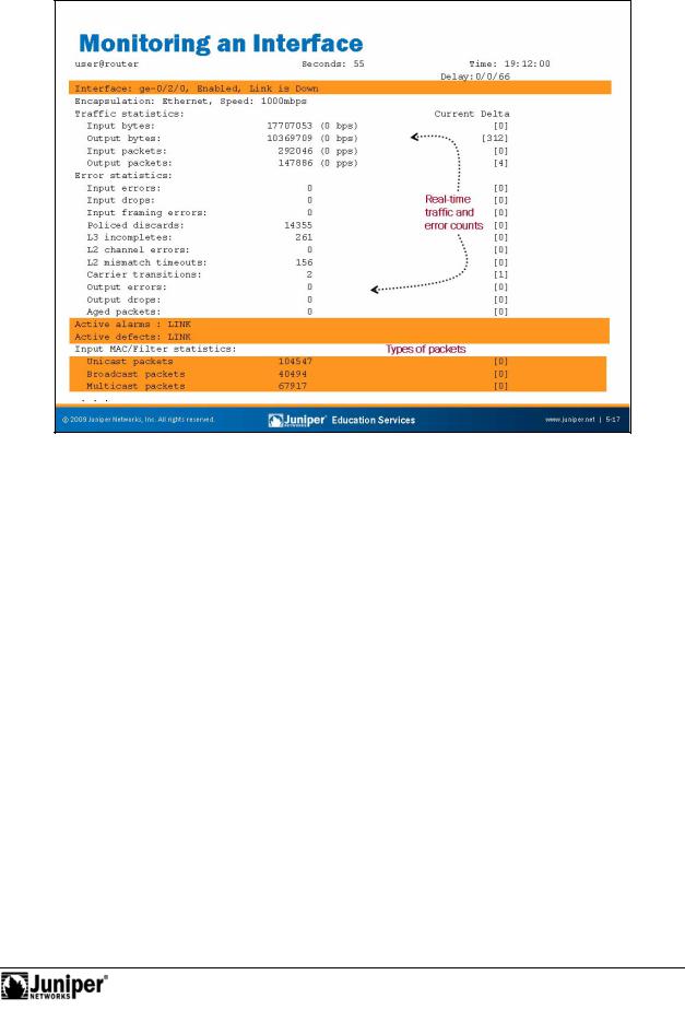
MonitoringReproductionan Int rface
The slide picts a typical output from the monitor interface command. You must set your t rminal s ssion to VT100 for the screen to display correctly. This command provides real-time packet and byte counters as well as displaying error and
forala m conditions. Not
Interface Troubleshooting • Chapter 5–17
Troubleshooting JUNOS Platforms
Not
Reproduction |
|
|
|
|
|||
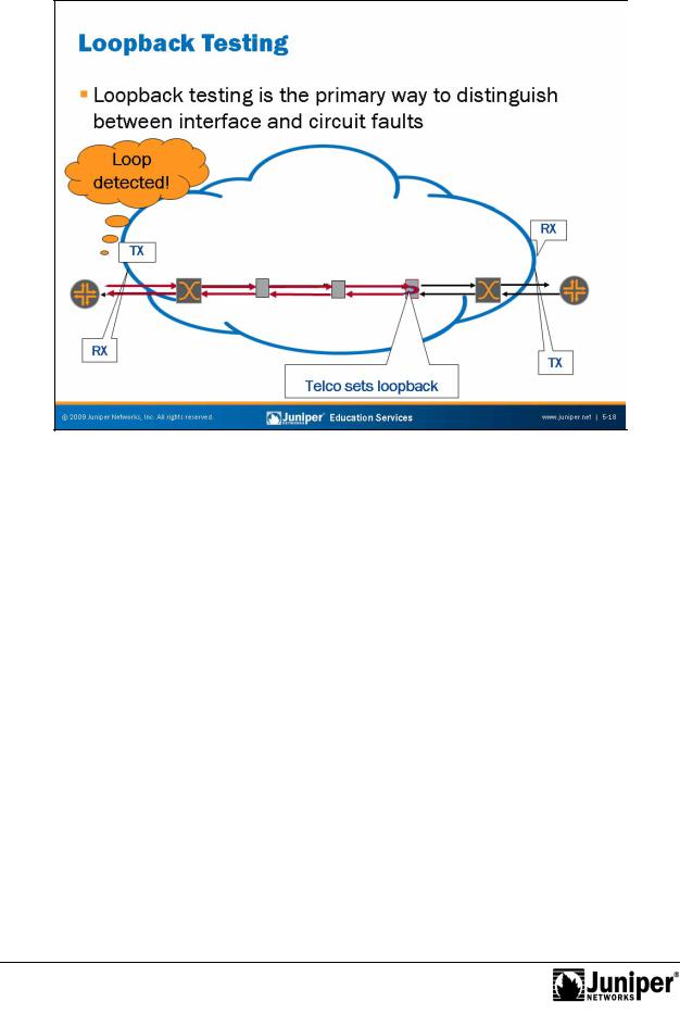
Loopback Testing |
|
|
|
The physical path of a l |
as line usually consists of a number of segments or spans |
||
interconnected by d vic |
s that r p at and regenerate the signal. When a fault occurs |
||
on the circuit that takes the form of either a break or signal corruption due to noise, it is possible to localize the problem by testing the line on a segment-by-segment basis
foror an end-to-end basis, as needed.
Each ci cuit is symmetric in that a transmit path from one device connects to the receive path n the remote side, and vice versa. Looping is the process of connecting the transmit path of a router or intermediate device to the receive path. If this device is ne the r uters, the loop is either detected if the looped segment is operational, or not detected if a break occurs. The device achieves this detection by detecting its own Data Link Layer keepalive packets (for example, the magic number when the encapsulation is PPP).
If a loop is set back towards a device and the device does not detect it, you can assume that the problem lies somewhere between the device and where the loop was set by the telco or provider. The next step is to set a loop somewhere closer to the device to localize the problem segment.
Continued on next page.
Chapter 5–18 • Interface Troubleshooting

Troubleshooting JUNOS Platforms
Loopback Testing (contd.)
It is usually possible to loop the device interface locally by connecting the PIC’s transmit and receive ports. You should take care to attenuate signal strength when dealing with intermediate-reach and long-reach fiber-optic interfaces.
|
You can use a similar approach to track down noise on a line by combining the looping |
|
|
process with a test that checks for bit rate errors, commonly known as BERT testing. |
|
|
Many of the interfaces JUNOS platforms support BERT testing. |
|
|
for |
Reproduction |
Not |
|
|
|
|
|
Interface Troubleshooting • Chapter 5–19
Troubleshooting JUNOS Platforms
|
rem te l pbackReproductionequest to the remote device. Line loops can be remotely |
|
||
|
signalled |
|||
|
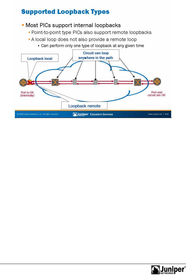
Supported Loopback Ty |
s |
||
|
Most PICs supported |
JUNOS platforms support local (internal) loopback tests. |
||
|
Where possible, it is b |
st to p |
rform local loopbacks using an external loopback plug |
|
because this setup also tests the PIC’s transmit and receive circuitry. Point-to-point forstyle inte faces (nonbroadcast types of technologies like SONET or
T1/DS1), also support remote loopbacks. Note that configuring an interface for a remote loopback esults in a line loop on the local device; it does not generate a
PICs with integral channel service unit (CSU) functionality (T1 or E1, and T3 or E3),
but the generation of the remote loopback code requires telco interaction or test Not
equipment. Again, configuring a remote loopback in JUNOS Software does not signal he remote end to perform a loopback; it creates a local line-loop condition.
For local loopback the PIC’s transmit clocking should be set to internal, which is the default setting. A remote loopback (or line loop) allows telco testing on the local loop (also referred to as the tail) and also allows testing from the remote device.
Chapter 5–20 • Interface Troubleshooting