

Chapter 6 |
Analog Input |
Simple-Buffered Analog Input with a
Write to Spreadsheet File
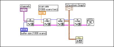
If you want to write the acquired data to a file, there are many file formats in which you can store the data. The spreadsheet file format is used most often because you can read it using most spreadsheet applications for later data graphing and analysis. In LabVIEW, you can use VIs to send data to a file in spreadsheet format or read back data from such a file. You can find these VIs on the Functions»File I/O palette and on the Functions» Waveform»Waveform File I/O palette. The VI used in this example is the Export Waveforms to Spreadsheet File VI, shown in Figure 6-17. In this exercise, the Intermediate analog input VIs acquire an array of waveform data, graph the data, and create a spreadsheet file containing the data.
Figure 6-17. Writing to a Spreadsheet File after Acquisition
Using Circular Buffers to Access Your Data during Acquisition
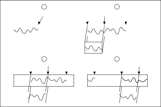
You can apply the simple buffering techniques in many DAQ applications, but there are some applications where these techniques are not appropriate. If you want to view, process, or log portions of your data as it is being acquired, do not use these simple-buffered techniques. For these types of applications, you should set up a circular buffer to store acquired data in memory. Figure 6-18 shows how a circular buffer works. Portions of data are read from the buffer while the buffer is being filled. Using a circular buffer, you can set up your device to continuously acquire data in the background while LabVIEW retrieves the acquired data.
© National Instruments Corporation |
6-25 |
LabVIEW Measurements Manual |
Chapter 6 |
Analog Input |
1 |
|
|
|
2 |
|
|
Incoming Data |
|
|
|
|
|
|
from the Board End of Data |
Current Read Mark |
End of Data |
||||
to the PC |
|
|
|
|
|
|
(AI Start.vi) |
|
|
|
|
|
|
|
|
|
|
|
||
|
|
|
|
|
|
|
|
|
|
|
|
|
|
Data transferred from PC buffer to LabVIEW
(AI Read.vi)
3 |
|
|
|
|
|
|
4 |
|
|
|
|
||
Current Read Mark End of Data |
End of Data |
Current Read Mark |
|||||||||||
|
|
|
|
|
|
|
|
|
|
|
|
|
|
|
|
|
|
|
|
|
|
|
|
|
|
|
|
|
|
|
|
|
|
|
|
|
|
|
|
|
|
|
|
|
|
|
|
|
|
|
|
|
|
|
|
|
|
|
|
|
|
|
|
|
|
|
|
|
|
Figure 6-18. How a Circular Buffer Works
A circular buffer differs from a simple buffer only in how LabVIEW places the data into it and retrieves data from it. A circular buffer is filled with data, just as a simple buffer. However, when it gets to the end of the buffer, it returns to the beginning and fills up the same buffer again. This means data can read continuously into computer memory, but only a defined amount of memory can be used. Your VI must retrieve data in blocks, from one location in the buffer, while the data enters the circular buffer at a different location, so that unread data is not overwritten by newer data. Because of the buffer maintenance, you can use only the Intermediate or Advanced VIs with this type of data acquisition.
While a circular buffer works well in many applications, there are two possible problems that can occur with this type of acquisition: Your VI could try to retrieve data from the buffer faster than data is placed into it, or your VI might not retrieve data from the buffer fast enough before LabVIEW overwrites the data into the buffer. When your VI tries to read data from the buffer that has not yet been collected, LabVIEW waits for the data your VI requested to be acquired and then returns the data. If your VI
LabVIEW Measurements Manual |
6-26 |
www.ni.com |

Chapter 6 |
Analog Input |
does not read the data from the circular buffer fast enough, the VI sends back an error, advising you that some data has been overwritten and lost.
Continuously Acquiring Data from Multiple Channels
You can acquire time-sampled data continuously from one or more channels with the Intermediate VIs. Refer to the Acquire & Process N Scans VI in the examples\daq\anlogin\anlogin.llb for an example using these VIs. Open this VI and examine its block diagram.
There are inputs for setting the channels, size of the circular buffer, scan rate, and the number of samples to retrieve from the circular buffer each time. This VI defaults to an input buffer size of 2,000 samples and 1,000 number of scans to read at a time, which means the VI reads in half of the buffer’s data while the VI fills the second half of the buffer with new data.
Note The number of scans to read can be any number less than the input buffer size.
If you do not retrieve data from the circular buffer fast enough, your unread data will be overwritten by newer data. You can resolve this problem by adjusting one of these three parameters: the input buffer size, the scan rate, or the number of scans to read at a time. If your program overwrites data in the buffer, then data is coming into the buffer faster than your VI can read all of the previous buffer data, and LabVIEW returns the error code –10846 overWriteError. If you increase the size of the buffer so that it takes longer to fill up, your VI has more time to read data from it. If you slow down the scan rate, you reduce the speed at which the buffer fills up, which also gives your program more time to retrieve data. You also can increase the number of scans to read at a time. This retrieves more data out of the buffer each time and effectively reduces the number of times to access the buffer before it becomes full. Check the output scan backlog to see how many data values remain in the circular buffer after the read.
Because this uses Intermediate VIs, you also can control other parameters such as triggering, coupling, and additional hardware.
Asynchronous Continuous Acquisition Using
DAQ Occurrences
The main advantage of acquiring data as described in the previous section is that you are free to manipulate your data between calls to the AI Read VI. One limitation, however, is that the acquisition is synchronous. This means that once you call the AI Read VI, you cannot perform any other tasks until
© National Instruments Corporation |
6-27 |
LabVIEW Measurements Manual |
Chapter 6 |
Analog Input |
the AI Read VI returns your acquired data. If your DAQ device is still busy collecting data, you will have to sit idle until it finishes. On multithreaded platforms like Windows, this limitation can be worked around by allocating additional threads or by changing the preferred execution system of parts of your application.
Another alternative is to use asynchronous acquisition. You can acquire asynchronous continuous data from multiple channels using the same intermediate DAQ VIs by adding DAQ Occurrences. Refer to the Cont Acq&Chart (Async Occurrence) VI in the examples\daq\ anlogin\anlogin.llb for an example of asynchronous acquisition. Notice that it is very similar to the example described previously, the Acquire & Process N Scans VI.
The difference is that this example uses the DAQ Occurrence Config VI and the Wait on Occurrence function to control the reads. The first DAQ Occurrence Config VI sets the DAQ Event. In this example the DAQ Event is to set the occurrence every time a number of scans is
acquired equal to the value of general value A, where general value A is the number of scans to read at a time. Inside the While Loop, the Wait on Occurrence function sleeps in the background until the chosen DAQ Event takes place. Notice that the timed out output from the Wait on Occurrence function is wired to the selection terminal of the Case structure that encloses the AI Read VI. This means that AI Read is not called until the number of scans to read at a time have been acquired. The result is that the While Loop is effectively put to sleep, because you do not try to read the data until you know it has been acquired. This frees up the execution thread to do other tasks while you are waiting for the DAQ Event. If the DAQ Occurrence times out, the timed-out output value would be TRUE, and AI Read would never be called. When your acquisition is complete, DAQ Occurrence is called again to clear all occurrences.
Circular-Buffered Analog Input Examples
The only differences between the simple-buffered applications and circular-buffered applications in the block diagram is the setting of the number of scans to acquire input of the AI Start VI, and you must call the AI Read VI repeatedly to retrieve your data. These changes can be applied to many of the examples in the previous section on simple buffered analog input. However, this section reviews the basic circular-buffered analog input VI here and describes some other example VIs that are included with LabVIEW.
LabVIEW Measurements Manual |
6-28 |
www.ni.com |