

Chapter 6 |
Analog Input |
Amplitude (volts)
|
|
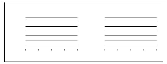
Range = 0 to 10 V |
|
|
|
|
|
|
|
|
Range = -10 to 10 V |
|
|
|
|||||||||||
10.00 |
|
|
|
|
|
|
|
|
|
|
|
|
|
|
|
10.00 |
|
|
|
|
|
|
|
|
|
|
111 |
|
|
|
|
|
|
|
|
|
|
|
|
111 |
|
|
|
|
|
|
|||||
8.75 |
|
|
|
|
|
|
|
|
|
|
|
(volts) |
7.50 |
|
|
|
|
|
|
|
|||||
|
|
|
110 |
|
|
|
|
|
|
|
|
|
|
|
|
110 |
|
|
|
|
|
|
|||
6.25 |
|
|
|
|
|
|
|
|
|
|
|
|
|
2.50 |
|
|
|
|
|
|
|
|
|||
7.50 |
|
|
101 |
|
|
|
|
|
|
|
|
|
|
|
5.00 |
|
101 |
|
|
|
|
|
|
||
|
|
001 |
|
|
|
|
|
|
|
|
|
|
Amplitude |
|
|
001 |
|
|
|
|
|
|
|||
5.00 |
|
100 |
|
|
|
|
|
|
|
|
|
|
|
0 |
|
100 |
|
|
|
|
|
|
|||
3.75 |
|
011 |
|
|
|
|
|
|
|
|
|
|
|
-2.50 |
|
011 |
|
|
|
|
|
|
|||
|
010 |
|
|
|
|
|
|
|
|
|
|
|
|
010 |
|
|
|
|
|
|
|||||
2.50 |
|
|
|
|
|
|
|
|
|
|
|
|
-5.00 |
|
|
|
|
|
|
|
|||||
|
|
|
|
|
|
|
|
|
|
|
|
|
|
|
|
|
|
|
|
|
|
|
|
||
1.25 |
|
000 |
|
|
|
|
|
|
|
|
|
|
|
-7.50 |
|
000 |
|
|
|
|
|
|
|||
|
|
|
|
|
|
|
|
|
|
|
|
|
|
|
|
|
|
||||||||
0 |
|
|
|
|
|
|
|
|
|
|
|
|
-10.00 |
|
|
|
|
|
|
|
|||||
|
50 |
100 |
|
|
150 |
200 |
|
|
50 |
100 |
150 |
200 |
|||||||||||||
0 |
|
|
|
0 |
|||||||||||||||||||||
|
|
|
|
|
Time (µs) |
|
|
|
|
|
|
|
|
|
|
Time (µs) |
|
|
|
||||||
|
|
|
|
|
|
|
|
|
|
|
|
|
|
|
|
|
|
|
|
|
|
|
|
|
|
Figure 6-5. The Effects of Range on ADC Precision
Signal Limit Settings
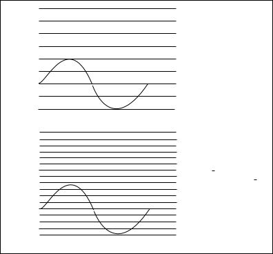
Limit settings are the maximum and minimum values of the signal you are measuring. A more precise limit setting allows the ADC to use more digital divisions to represent the signal. Figure 6-6 shows an example of this theory. Using a 3-bit ADC and a device range setting of 0.00 to 10.00 V, Figure 6-6 shows the effects of a limit setting between 0 and 5 V and 0 and 10 V. With a limit setting of 0 to 10 V, the ADC uses only four of the eight divisions in the conversion. But using a limit setting of 0 to 5 V, the ADC now has access to all eight digital divisions. This makes the digital representation of the signal more accurate.
© National Instruments Corporation |
6-5 |
LabVIEW Measurements Manual |
Chapter 6 |
Analog Input |
|
10.00 |
|
|
111 |
|
|
|
|
|
|
|
|
|
|
|
|
|
|
|
|
|
|
|
|
|
|
|
|
|
|
|
|
|
|
|
|
|
|
|
|
|
|
|
|
|
|
|||
|
8.75 |
|
|
|
|
|
|
|
|
|
|
|
|
|
|
|
|
|
|
|
|
|
||
|
|
|
110 |
|
|
|
|
|
|
|
|
|
|
|
|
|
|
|
|
|
|
|
||
|
7.5 |
|
|
|
|
|
|
|
|
|
|
|
|
|
|
|
|
|
|
|
|
|
||
|
|
|
101 |
|
|
|
|
|
|
|
|
|
|
|
|
|
|
|
|
|
|
|
||
|
6.25 |
|
|
|
|
|
|
|
|
|
|
|
|
|
|
|
|
|
|
|
|
|
||
|
|
|
|
|
|
|
|
|
|
|
|
|
|
|
|
|
|
|
|
|
||||
V |
|
|
100 |
|
|
|
|
|
|
|
|
|
|
|
|
|
|
|
|
|
|
|
||
5.00 |
|
|
|
|
|
|
|
|
|
|
|
|
|
|
|
|
|
|
|
|
|
|||
|
|
011 |
|
|
|
|
|
|
|
|
|
|
|
|
|
|
|
|
|
|
|
|||
|
3.75 |
|
|
|
|
|
|
|
|
|
|
|
|
|
|
|
|
|
|
|
|
|
||
|
|
|
010 |
|
|
|
|
|
|
|
|
|
|
|
|
|
|
|
|
|
|
|
||
|
2.50 |
|
|
|
|
|
|
|
|
|
|
|
|
|
|
|
|
|
|
|
|
|
||
|
|
|
|
|
|
|
|
|
|
|
|
|
|
|
|
|
|
|
|
|
|
|
|
|
|
|
001 |
Limit Settings 0 to 10 V |
|||||||||||||||||||||
|
1.25 |
|
|
|||||||||||||||||||||
|
|
|
|
|
|
|
|
|
|
|
|
|
|
|
|
|
|
|
|
|
|
|
|
|
|
0.00 |
|
|
000 |
|
|
|
|
|
|
|
|
|
|
|
|
|
|
|
|
|
|
|
|
|
|
|
|
|
|
|
|
|
|
|
|
|
|
|
|
|
|
|
|
|
|
|
|
|
|
10.00 |
|
|
|
|
|
|
|
|
|
|
|
|
|
|
|
|
|
|
|
|
|
|
|
|
|
|
|
|
|
|
|
|
|
|
|
|
|
|
|
|
|
|
|
|
|
|
||
|
8.75 |
|
|
|
|
|
|
|
|
|
|
|
|
|
|
|
|
|
|
|
|
|
|
|
|
7.5 |
|
|
|
|
|
|
|
|
|
|
|
|
|
|
|
|
|
|
|
|
|
|
|
|
|
|
|
|
|
|
|
|
|
|
|
|
|
|
|
|
|
|
|
|
|
|
||
V |
6.25 |
|
|
|
|
|
|
|
|
|
|
|
|
|
|
|
|
|
|
|
|
|
|
|
|
|
|
|
|
|
|
|
|
|
|
|
|
|
|
|
|
|
|
|
|
|
|
||
|
|
|
|
|
|
|
|
|
|
|
|
|
|
|
|
|
|
|
|
|
|
|||
5.00 |
|
|
|
111 |
|
|
|
|
|
|
|
|
|
|
|
|
|
|
|
|
|
|
|
|
|
|
|
|
|
|
|
|
|
|
|
|
|
|
|
|
|
|
|
|
|
||||
|
3.75 |
|
|
|
110 |
|
|
|
|
|
|
|
|
|
|
|
|
|
|
|
|
|
|
|
|
|
|
|
101 |
|
|
|
|
|
|
|
|
|
|
|
|
|
|
|
|
|
|
|
|
|
|
|
|
|
|
|
|
|
|
|
|
|
|
|
|
|
|
|
|
|
|
|||
|
|
|
|
|
Limit Settings 0 to 5 V |
|||||||||||||||||||
|
2.50 |
|
|
|
100 |
|||||||||||||||||||
|
|
|
|
011 |
|
|
|
|
|
|
|
|
|
|
|
|
|
|
|
|
|
|
|
|
|
|
|
|
|
|
|
|
|
|
|
|
|
|
|
|
|
|
|
|
|
|
|
|
|
|
1.25 |
|
|
|
010 |
|
|
|
|
|
|
|
|
|
|
|
|
|
|
|
|
|
|
|
|
|
|
|
001 |
|
|
|
|
|
|
|
|
|
|
|
|
|
|
|
|
|
|
|
|
|
|
|
|
|
|
|
|
|
|
|
|
|
|
|
|
|
|
|
|
|
|
|
|
|
|
0.00 |
|
|
|
000 |
|
|
|
|
|
|
|
|
|
|
|
|
|
|
|
|
|
|
|
|
|
|
|
|
|
|
|
|
|
|
|
|
|
|
|
|
|
|
|
|
|
|||
Limit Settings 0 to 5 V
Figure 6-6. The Effects of Limit Settings on ADC Precision
Considerations for Selecting Analog Input Settings
The resolution and device range of a DAQ device determine the smallest detectable change in the input signal. You can calculate the smallest detectable change, called the code width, using the following formula.
device range code width = ----------------------------------
2resolution
LabVIEW Measurements Manual |
6-6 |
www.ni.com |
Chapter 6 |
Analog Input |
For example, a 12-bit DAQ device with a 0 to 10 V input range detects a 2.4 mV change, while the same device with a –10 to 10 V input range detects only a change of 4.8 mV.
device--------------------range-------------- |
= |
-10----- |
= 2.4 |
mV |
2resolution |
|
212 |
|
|
device--------------------range-------------- |
= |
-20----- |
= 4.8 |
mV |
2resolution |
|
212 |
|
|
A high-resolution A/D converter provides a smaller code width given the device voltage ranges shown above.
device--------------------range-------------- |
= |
-10----- |
= .15 mV |
2resolution |
|
216 |
|
device--------------------range-------------- |
= |
-20----- |
= .3 mV |
2resolution |
|
216 |
|
The smaller your code width, the more accurate your measurements will be.
There are times you must know whether your signals are unipolar or bipolar. Unipolar signals are signals that range from 0 value to a positive value (for example, 0 to 5 V). Bipolar signals are signals that range from a negative to a positive value (for example, –5 to 5 V). To achieve a smaller code width if your signal is unipolar, specify that the device range is unipolar, as shown previously. If your signal range is smaller than the device range, set your limit settings to values that more accurately reflect your signal range. Table 6-1 shows how the code width of the 12-bit DAQ devices varies with device ranges and limit settings, because your limit settings automatically adjust the gain on your device.
© National Instruments Corporation |
6-7 |
LabVIEW Measurements Manual |