

Chapter 10 High-Precision Timing (Counters/Timers)
the other measurement by taking the inverse of the current one as shown in the following equations.
1
period measurement = -----------------------------------------------------------
frequency measurement
1 frequency measurement = --------------------------------------------------
period measurement
8253/54
The 8253/54 chip does not support period measurement, but you can use frequency measurement for a pulse train and take the inverse to get the period. The frequency examples discussed in this chapter calculate the period for you.
Connecting Counters to Measure Frequency and Period
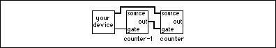
Figure 10-21 shows typical external connections for measuring frequency. In the figure, your device provides the signal with the frequency to be measured to the SOURCE (CLK) of counter. It optionally can control the GATE of counter-1. The OUT of counter-1 supplies a known pulse to the GATE of counter. Finally, counter counts the number of cycles of the unknown pulse during the known GATE pulse.
Figure 10-21. External Connections for Frequency Measurement
LabVIEW Measurements Manual |
10-24 |
www.ni.com |
Chapter 10 High-Precision Timing (Counters/Timers)
TIO-ASIC, DAQ-STC, Am9513
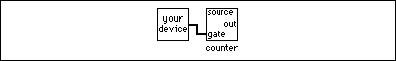
Figure 10-22 shows typical external connections for measuring period. In the figure, your device provides the signal with the period to be measured to the GATE of counter. A timebase of known frequency is supplied to the SOURCE. This usually is an internal timebase, but it can be externally supplied. The counting range of your counter must not be exceeded during the period measurement. The range of the Am9513 is 65,335; the range of the DAQ-STC is 16,777,216; and the range of the TIO-ASIC is 232–1. If the counting range is exceeded, select a slower internal timebase.
Figure 10-22. External Connections for Period Measurement
Measuring the Frequency and Period of High-Frequency Signals
How you measure the frequency and period of high-frequency signals (higher than 1000 Hz) depends on the counter chip on your DAQ device. If you are not sure which chip your DAQ device has, refer to your hardware user manual.
TIO-ASIC, DAQ-STC
Open the Measure Frequency (DAQ-STC) and Measure Frequency (NI-TIO) VIs in the examples\daq\counter library and study the block diagrams.
The counter counts the number of rising edges of a TTL signal at the SOURCE of counter during a known pulse at the GATE of counter. The width of that known pulse is determined by gate width. Frequency is the output for this example, and period is calculated by taking the inverse of the frequency.
Am9513
Refer to the Measure Frequency-Easy (9513) VI in the examples\daq\ counter\Am9513.llb for an example of how to use the Easy VI, Measure Frequency, available on the Functions»Data Acquisition» Counter palette.
© National Instruments Corporation |
10-25 |
LabVIEW Measurements Manual |
Chapter 10 High-Precision Timing (Counters/Timers)
This VI initiates the counter to count the number of rising edges of a TTL signal at the SOURCE of counter during a known pulse at the GATE of counter. The width of that known pulse is determined by gate width. Frequency is the output for this example, and period is calculated by taking the inverse of the frequency. The valid? output lets you know if the measurement completed without an overflow. The number of counters to use input lets you choose one counter for 16-bit measurement or two counters for 32-bit measurement. Remember, you must externally
wire your signal to be measured to the SOURCE of counter, and the OUT of counter-1 must be wired to the GATE of counter.
TIO-ASIC, DAQ-STC, Am9513
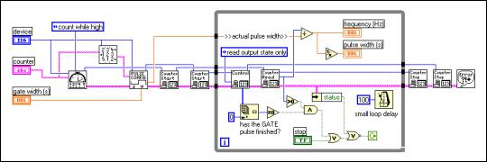
If you need more control over when your frequency measurement begins and ends, use the Intermediate VIs instead of the Easy VIs. Figure 10-23 shows one approach for this that uses the Event or Time Counter Config, Adjacent Counters, Delayed Pulse Generator Config, Counter Start, CTR Control, Counter Read, and Counter Stop VIs. The Delayed Pulse Generator Config VI configures counter to count the number of pulses
while its GATE is high. The Adjacent Counters VI is used to determine the correct counter-1. The Delayed Pulse Generator Config VI then configures counter-1 to generate a single pulse for the GATE signal. The Counter Start VI begins the counting operation for counter first, then counter-1. The CTR Control VI is an Advanced VI that is used to check if the GATE pulse has completed. The Counter Read VI returns the count value from counter, which is used to determine the frequency and pulse width. Finally, the Counter Stop VI stops the counter operation.
Figure 10-23. Frequency Measurement Example Using Intermediate VIs
LabVIEW Measurements Manual |
10-26 |
www.ni.com |
Chapter 10 High-Precision Timing (Counters/Timers)
8253/54
Refer to the Measure Hi Frequency (8253) VI in the examples\daq\ counter\8253.llb for an example of how to initiate the counter to count the number of rising edges of a TTL signal at the CLK of counter during a known pulse at the GATE of counter. The known pulse is created by counter 0, and its width is determined by gate width. The maximum width of the pulse is 32 ms if your DAQ device has a 2 MHz internal timebase, and 65 ms if your DAQ device has a 1 MHz internal timebase. This maximum pulse is why this example only reads frequencies higher than 1 kHz. A frequency of 1 kHz generates 32 cycles during the 32 ms pulse. As this cycle count decreases (as with lower frequencies), the frequency measurement becomes less accurate. Frequency is the output for this example, and period is determined by taking the inverse of the frequency. You must externally wire the signal to be measured to the CLK of counter, and the OUT of counter 0 must be wired through a 7404 inverter chip to the GATE of counter.
Notice the ICTR Control, Get Timebase (8253), and Wait + (ms) VIs on the block diagram. The first two ICTR Control VIs reset counter and counter 0. The next ICTR Control sets up counter to count down while its GATE input is high. The Get Timebase (8253) VI returns the internal timebase period for counter 0 of the device. This value is multiplied by the gate width to yield the count to be loaded into the count register of counter 0. The next ICTR Control VI loads this count and sets up counter 0 to output a low pulse, during which cycles of the signal to be measured are counted.
One advantage of this example is that it uses only two counters. However, this example has two notable limitations. One limitation is that it cannot accurately measure low frequencies. Refer to the Measure Lo Frequency (8253) VI in the examples\daq\counter\8253.llb if you need to measure lower frequencies. This VI uses three counters. The other limitation is that there is a software dependency, which causes counter 0 to output a pulse slightly longer than the count it is given. This is the nature of the 8253 chip, and it can increase the readings of high frequencies. Use the Measure Hi Frequency–DigStart (8253) VI in the examples\daq\ counter\8253.llb to avoid this software delay.
© National Instruments Corporation |
10-27 |
LabVIEW Measurements Manual |