

- •CONTENTS
- •Preface
- •To the Student
- •Diagnostic Tests
- •1.1 Four Ways to Represent a Function
- •1.2 Mathematical Models: A Catalog of Essential Functions
- •1.3 New Functions from Old Functions
- •1.4 Graphing Calculators and Computers
- •1.6 Inverse Functions and Logarithms
- •Review
- •2.1 The Tangent and Velocity Problems
- •2.2 The Limit of a Function
- •2.3 Calculating Limits Using the Limit Laws
- •2.4 The Precise Definition of a Limit
- •2.5 Continuity
- •2.6 Limits at Infinity; Horizontal Asymptotes
- •2.7 Derivatives and Rates of Change
- •Review
- •3.2 The Product and Quotient Rules
- •3.3 Derivatives of Trigonometric Functions
- •3.4 The Chain Rule
- •3.5 Implicit Differentiation
- •3.6 Derivatives of Logarithmic Functions
- •3.7 Rates of Change in the Natural and Social Sciences
- •3.8 Exponential Growth and Decay
- •3.9 Related Rates
- •3.10 Linear Approximations and Differentials
- •3.11 Hyperbolic Functions
- •Review
- •4.1 Maximum and Minimum Values
- •4.2 The Mean Value Theorem
- •4.3 How Derivatives Affect the Shape of a Graph
- •4.5 Summary of Curve Sketching
- •4.7 Optimization Problems
- •Review
- •5 INTEGRALS
- •5.1 Areas and Distances
- •5.2 The Definite Integral
- •5.3 The Fundamental Theorem of Calculus
- •5.4 Indefinite Integrals and the Net Change Theorem
- •5.5 The Substitution Rule
- •6.1 Areas between Curves
- •6.2 Volumes
- •6.3 Volumes by Cylindrical Shells
- •6.4 Work
- •6.5 Average Value of a Function
- •Review
- •7.1 Integration by Parts
- •7.2 Trigonometric Integrals
- •7.3 Trigonometric Substitution
- •7.4 Integration of Rational Functions by Partial Fractions
- •7.5 Strategy for Integration
- •7.6 Integration Using Tables and Computer Algebra Systems
- •7.7 Approximate Integration
- •7.8 Improper Integrals
- •Review
- •8.1 Arc Length
- •8.2 Area of a Surface of Revolution
- •8.3 Applications to Physics and Engineering
- •8.4 Applications to Economics and Biology
- •8.5 Probability
- •Review
- •9.1 Modeling with Differential Equations
- •9.2 Direction Fields and Euler’s Method
- •9.3 Separable Equations
- •9.4 Models for Population Growth
- •9.5 Linear Equations
- •9.6 Predator-Prey Systems
- •Review
- •10.1 Curves Defined by Parametric Equations
- •10.2 Calculus with Parametric Curves
- •10.3 Polar Coordinates
- •10.4 Areas and Lengths in Polar Coordinates
- •10.5 Conic Sections
- •10.6 Conic Sections in Polar Coordinates
- •Review
- •11.1 Sequences
- •11.2 Series
- •11.3 The Integral Test and Estimates of Sums
- •11.4 The Comparison Tests
- •11.5 Alternating Series
- •11.6 Absolute Convergence and the Ratio and Root Tests
- •11.7 Strategy for Testing Series
- •11.8 Power Series
- •11.9 Representations of Functions as Power Series
- •11.10 Taylor and Maclaurin Series
- •11.11 Applications of Taylor Polynomials
- •Review
- •APPENDIXES
- •A Numbers, Inequalities, and Absolute Values
- •B Coordinate Geometry and Lines
- •E Sigma Notation
- •F Proofs of Theorems
- •G The Logarithm Defined as an Integral
- •INDEX

SECTION 8.3 APPLICATIONS TO PHYSICS AND ENGINEERING |||| 539
1. Show that the area of is |
|
|
|
1 |
q |
|
|
|
|
yp |
f x mx b 1 mf x dx |
|
1 m 2 |
||
[Hint: This formula can be verified by subtracting areas, but it will be helpful throughout the project to derive it by first approximating the area using rectangles perpendicular to the line, as shown in the figure. Use the figure to help express u in terms of x.]
tangent to C |
? |
? |
||
|
|
|||
at {xi, f(xi)} |
|
|
||
|
|
|
y=mx+b |
|
|
|
|
|
Îu |
å |
|
|
|
xi ∫ |
|
|
Îx |
|
|
|
|
|
|
|
|
|
|
||
y |
(2π,2π) |
|
y=x+sin x |
|
y=x-2 |
0 |
x |
2.Find the area of the region shown in the figure at the left.
3.Find a formula similar to the one in Problem 1 for the volume of the solid obtained by rotating about the line y mx b.
4.Find the volume of the solid obtained by rotating the region of Problem 2 about the line y x 2.
5.Find a formula for the area of the surface obtained by rotating C about the line y mx b.
CAS 6. Use a computer algebra system to find the exact area of the surface obtained by rotating the curve y sx , 0 x 4, about the line y 12 x. Then approximate your result to three decimal places.
surface of fluid
FIGURE 1
8.3APPLICATIONS TO PHYSICS AND ENGINEERING
Among the many applications of integral calculus to physics and engineering, we consider two here: force due to water pressure and centers of mass. As with our previous applications to geometry (areas, volumes, and lengths) and to work, our strategy is to break up the physical quantity into a large number of small parts, approximate each small part, add the results, take the limit, and then evaluate the resulting integral.
HYDROSTATIC FORCE AND PRESSURE
Deep-sea divers realize that water pressure increases as they dive deeper. This is because the weight of the water above them increases.
In general, suppose that a thin horizontal plate with area A square meters is submerged in a fluid of density kilograms per cubic meter at a depth d meters below the surface of the fluid as in Figure 1. The fluid directly above the plate has volume V Ad, so its mass is m V Ad. The force exerted by the fluid on the plate is therefore
F mt tAd

540 |||| CHAPTER 8 FURTHER APPLICATIONS OF INTEGRATION
N When using US Customary units, we write
P |
|
td |
|
|
d, where |
|
|
|
t is the weight |
|||
|
|
|
|
|
||||||||
density (as opposed to |
|
, which is the mass |
||||||||||
|
||||||||||||
density). For instance, the weight density of |
||||||||||||
water is |
|
|
|
|
|
3 |
. |
|
|
|
||
|
62.5 lb ft |
|
|
|
||||||||
50 m
20 m
30 m
FIGURE 2
_4 15 10
Îx 

15
x
(a)
10
a
20
16-xi
(b)
FIGURE 3
where t is the acceleration due to gravity. The pressure P on the plate is defined to be the force per unit area:
P F td
A
The SI unit for measuring pressure is newtons per square meter, which is called a pascal (abbreviation: 1 N m2 1 Pa). Since this is a small unit, the kilopascal (kPa) is often used. For instance, because the density of water is 1000 kg m3, the pressure at the bottom of a swimming pool 2 m deep is
P td 1000 kg m3 9.8 m s2 2 m
19,600 Pa 19.6 kPa
An important principle of fluid pressure is the experimentally verified fact that at any point in a liquid the pressure is the same in all directions. (A diver feels the same pressure on nose and both ears.) Thus the pressure in any direction at a depth d in a fluid with mass
density is given by |
|
1 |
P td d |
This helps us determine the hydrostatic force against a vertical plate or wall or dam in a fluid. This is not a straightforward problem because the pressure is not constant but increases as the depth increases.
V EXAMPLE 1 A dam has the shape of the trapezoid shown in Figure 2. The height is 20 m, and the width is 50 m at the top and 30 m at the bottom. Find the force on the dam due to hydrostatic pressure if the water level is 4 m from the top of the dam.
SOLUTION We choose a vertical x-axis with origin at the surface of the water as in Figure 3(a). The depth of the water is 16 m, so we divide the interval 0, 16 into subintervals of equal length with endpoints xi and we choose xi* xi 1, xi . The ith horizontal strip of the dam is approximated by a rectangle with height x and width wi , where, from similar triangles in Figure 3(b),
|
a |
|
|
10 |
or a |
16 xi* |
8 |
xi* |
|
16 xi* |
20 |
2 |
2 |
||||
and so |
wi |
2 15 a 2(15 8 21 xi*) 46 xi* |
||||||
If Ai is the area of the ith strip, then
Ai wi x 46 xi* x
If x is small, then the pressure Pi on the ith strip is almost constant and we can use Equation 1 to write
Pi 1000txi*
The hydrostatic force Fi acting on the ith strip is the product of the pressure and the area:
Fi Pi Ai 1000txi* 46 xi* x

SECTION 8.3 APPLICATIONS TO PHYSICS AND ENGINEERING |||| 541
Adding these forces and taking the limit as n l , we obtain the total hydrostatic force on the dam:
n
F lim 1000txi* 46 xi* x
n l i 1
y16 1000tx 46 x dx
0
|
16 |
46x x2 dx |
||
1000 9.8 y0 |
||||
|
|
|
3 |
0 |
|
|
|
x3 |
16 |
9800 23x2 |
|
|
|
|
4.43 107 |
N |
|
|
M |
|
y |
7 |
œ |
|
|
|
Î |
0  x
x
≈ ¥ =9 |
EXAMPLE 2 Find the hydrostatic force on one end of a cylindrical drum with radius 3 ft if the drum is submerged in water 10 ft deep.
SOLUTION In this example it is convenient to choose the axes as in Figure 4 so that the origin is placed at the center of the drum. Then the circle has a simple equation,
x2 y2 9. As in Example 1 we divide the circular region into horizontal strips of equal width. From the equation of the circle, we see that the length of the ith strip is 2s9 yi* 2 and so its area is
Ai 2s9 yi* 2 y
The pressure on this strip is approximately
di 62.5 7 yi*
FIGURE 4 |
and so the force on the strip is approximately |
|
|
|
|
||
|
di Ai 62.5 7 yi* 2s |
|
y |
||||
|
9 yi* 2 |
||||||
|
The total force is obtained by adding the forces on all the strips and taking the limit: |
||||||
|
n |
62.5 7 yi* 2 |
s |
|
|
|
|
|
F lim |
9 yi* 2 |
y |
||||
|
n l |
|
|
|
|
|
|
|
i 1 |
|
|
|
|
|
|
125 y33 7 y s9 y2 dy
125 7 y33 s9 y2 dy 125 y33 ys9 y2 dy
The second integral is 0 because the integrand is an odd function (see Theorem 5.5.7). The first integral can be evaluated using the trigonometric substitution y 3 sin , but it’s simpler to observe that it is the area of a semicircular disk with radius 3. Thus
F875 y33
7875
s9 y2 dy
12,370 lb
875 21 |
3 2 |
M
2
542 |||| |
|
|
CHAPTER 8 |
FURTHER APPLICATIONS OF INTEGRATION |
|
|
|
|
|
|
|
|
|
|
|
|
|
|
|
|
|
||||||||||||||
|
|
|
|
|
|
|
|
|
|
|
|
|
|
|
|
MOMENTS AND CENTERS OF MASS |
|||||||||||||||||||
|
|
|
|
|
|
|
|
|
P |
|
|
|
|
|
Our main objective here is to find the point P on which a thin plate of any given shape bal- |
||||||||||||||||||||
|
|
|
|
|
|
|
|
|
|
|
|
|
|
ances horizontally as in Figure 5. This point is called the center of mass (or center of grav- |
|||||||||||||||||||||
|
|
|
|
|
|
|
|
|
|
|
|
|
|
|
|
||||||||||||||||||||
|
|
|
|
|
|
|
|
|
|
|
|
|
|
|
|
ity) of the plate. |
|
|
|
|
|
|
|
|
|
|
|
|
|
|
|
|
|
||
|
|
|
|
|
|
|
|
|
|
|
|
|
|
|
|
We first consider the simpler situation illustrated in Figure 6, where two masses m1 and |
|||||||||||||||||||
|
|
|
|
|
|
|
|
|
|
|
|
|
|
|
|
m2 are attached to a rod of negligible mass on opposite sides of a fulcrum and at distances |
|||||||||||||||||||
|
|
|
|
|
|
|
|
|
|
|
|
|
|
|
|
d1 and d2 from the fulcrum. The rod will balance if |
|||||||||||||||||||
FIGURE 5 |
|
|
|
|
|
|
|
|
|
|
2 |
|
|
|
|
|
|
m1d1 m2d2 |
|||||||||||||||||
|
|
|
|
|
|
|
|
|
|
|
|
|
|
|
|
|
|
|
|
|
|
||||||||||||||
|
|
|
|
d¡ |
|
|
|
|
|
d™ |
|
|
|
|
|
This is an experimental fact discovered by Archimedes and called the Law of the Lever. |
|||||||||||||||||||
|
|
|
|
|
|
|
|
|
|
|
|
|
|||||||||||||||||||||||
|
|
|
|
|
|
|
|
|
|
|
|
|
|
|
|
(Think of a lighter person balancing a heavier one on a seesaw by sitting farther away from |
|||||||||||||||||||
m¡ |
|
|
|
|
|
m™ |
|||||||||||||||||||||||||||||
|
|
|
|
|
the center.) |
|
|
|
|
|
|
|
|
|
|
|
|
|
|
|
|
|
|||||||||||||
|
|
|
|
|
|
|
|
|
|
|
|
|
|
|
|
Now suppose that the rod lies along the x-axis with m1 at x1 and m2 at x2 and the center |
|||||||||||||||||||
|
|
|
|
|
|
|
|
|
|
|
|
|
|
|
|
of mass at |
|
. If we compare Figures 6 and 7, we see that d1 |
|
x1 and d2 x2 |
|
and |
|||||||||||||
|
|
|
|
|
fulcrum |
|
|
|
|
|
x |
x |
x |
||||||||||||||||||||||
|
|
|
|
|
|
|
|
|
|
so Equation 2 gives |
|
|
|
|
|
|
|
|
|
|
|
|
|
|
|
|
|
||||||||
FIGURE 6 |
|
|
|
|
|
|
|
|
|
|
|
|
|
|
|
|
|
|
|
|
|
|
|
|
|
|
|
|
|
|
|||||
|
|
|
|
|
|
|
|
|
|
|
|
|
m1 x x1 m2 x2 x |
||||||||||||||||||||||
|
|
|
|
|
|
|
|
|
|
|
|
|
|
|
|
|
|
|
|||||||||||||||||
|
|
|
|
|
|
|
|
|
|
|
|
|
|
|
|
|
|
|
m1 |
|
|
m2 |
|
m1 x1 m2 x2 |
|||||||||||
|
|
|
|
|
|
|
|
|
|
|
|
|
|
|
|
|
|
|
x |
x |
|||||||||||||||
|
|
|
|
|
|
|
|
|
|
|
|
|
|
|
|
3 |
|
|
|
|
|
|
|
|
|
|
|
m1 x1 m2 x2 |
|
|
|
|
|
||
|
|
|
|
|
|
|
|
|
|
|
|
|
|
|
|
|
|
|
|
|
x |
||||||||||||||
|
|
|
|
|
|
|
|
|
|
|
|
|
|
|
|
|
|
|
|
|
m1 m2 |
||||||||||||||
|
|
|
|
|
|
|
|
|
|
|
|
|
|
|
|
|
|
|
|
|
|
|
|
|
|
|
|
||||||||
The numbers m1 x1 and m2 x2 are called the moments of the masses m1 and m2 (with respect to the origin), and Equation 3 says that the center of mass x is obtained by adding the moments of the masses and dividing by the total mass m m1 m2.
|
⁄ |
– |
|
¤ |
|
|
x |
|
|
||
0 |
m¡ |
x–-⁄ |
¤-x– |
m™ |
x |
|
|
||||
|
|
|
|
FIGURE 7
In general, if we have a system of n particles with masses m1, m2, . . . , mn located at the points x1, x2, . . . , xn on the x-axis, it can be shown similarly that the center of mass of the system is located at
|
|
|
|
n |
|
n |
|
|
|
|
|
mi xi |
|
mi xi |
|
4 |
|
|
|
i 1 |
|
i 1 |
|
x |
|||||||
|
n |
m |
|||||
|
|
|
|
mi |
|
||
|
|
|
|
|
|
i 1
where m mi is the total mass of the system, and the sum of the individual moments
n
M mi xi
i 1
is called the moment of the system about the origin. Then Equation 4 could be rewritten as mx M, which says that if the total mass were considered as being concentrated at the center of mass x, then its moment would be the same as the moment of the system.

SECTION 8.3 APPLICATIONS TO PHYSICS AND ENGINEERING |||| 543
y |
|
⁄ |
|
Now we consider a system of n particles with masses m1, m2, . . . , mn located at the |
|
|
|
||||
‹ |
|
|
points x1, y1 , x2, y2 , . . . , xn, yn in the xy-plane as shown in Figure 8. By analogy with |
||
|
m¡ |
|
|||
m£ |
|
› |
|
the one-dimensional case, we define the moment of the system about the y-axis to be |
|
y£ |
|
|
|
|
|
|
|
|
|
|
|
0 |
|
fi |
x |
|
n |
|
|
m™ |
|
5 |
My mi xi |
|
|
¤ |
|
|
i 1 |
FIGURE 8 |
|
|
|
and the moment of the system about the x-axis as |
|
|
|
|
|||
|
|
|
|
|
|
|
|
|
|
|
n |
|
|
|
|
6 |
Mx mi yi |
i 1
Then My measures the tendency of the system to rotate about the y-axis and Mx measures the tendency to rotate about the x-axis.
As in the one-dimensional case, the coordinates x, y of the center of mass are given in terms of the moments by the formulas
7 |
|
|
My |
|
|
|
Mx |
|
x |
y |
|||||||
m |
m |
|||||||
|
|
|
|
|
||||
where m mi is the total mass. Since mx My and my Mx , the center of massx, y is the point where a single particle of mass m would have the same moments as the system.
V EXAMPLE 3 Find the moments and center of mass of the system of objects that have masses 3, 4, and 8 at the points 1, 1 , 2, 1 , and 3, 2 , respectively.
SOLUTION We use Equations 5 and 6 to compute the moments:
|
|
|
|
|
|
|
|
|
|
|
|
|
|
|
|
My 3 1 4 2 8 3 29 |
||||||||||
|
|
|
|
y |
|
|
|
|
|
|
|
|
|
|
|
|
|
|
|
|
|
|
|
|
|
|
|
|
|
|
|
center of mass |
|
|
|
|
Mx 3 1 4 1 8 2 15 |
||||||||||||||||
|
|
|
|
|
|
|
|
|
|
8 |
|
|
|
|
|
|||||||||||
|
|
|
|
|
|
|
|
|
|
|
|
|
|
|
|
|
|
|
|
|
|
|
|
|
|
|
|
|
|
3 |
|
|
|
|
|
|
|
|
|
|
Since m 3 4 8 15, we use Equations 7 to obtain |
||||||||||||
|
|
|
|
|
|
|
|
|
|
|
|
|
|
|||||||||||||
|
|
|
|
|
|
|
|
|
|
|
|
|
|
|
|
|
|
|
|
|
|
|
|
|||
|
|
|
|
0 |
|
|
|
|
4 |
|
|
x |
|
|
|
My |
|
29 |
|
|
|
Mx |
|
15 |
|
|
|
|
|
|
|
|
|
|
|
|
|
|
|
|
|
|
|
|
|
|
|
|
1 |
||||
|
|
|
|
|
|
|
|
|
|
|
|
x |
y |
|||||||||||||
|
|
|
|
|
|
|
|
|
|
|
|
|
|
|
|
|
||||||||||
|
|
|
|
|
|
|
|
|
|
|
|
|
|
|
|
|
m |
15 |
|
|
|
m |
15 |
|
||
|
|
|
|
|
|
|
|
|
|
|
|
|
|
Thus the center of mass is (11514 , 1). (See Figure 9.) |
|
|
|
|||||||||
FIGURE 9 |
|
|
|
|
|
|
|
|
|
M |
||||||||||||||||
|
|
|
|
|
|
|
|
|
|
|
|
|
|
Next we consider a flat plate (called a lamina) with uniform density that occupies a |
||||||||||||
|
|
|
|
|
|
|
|
|
|
|
|
|
|
region of the plane. We wish to locate the center of mass of the plate, which is called |
||||||||||||
|
|
|
|
|
|
|
|
|
|
|
|
|
|
the centroid of . In doing so we use the following physical principles: The symmetry |
||||||||||||
|
|
|
|
|
|
|
|
|
|
|
|
|
|
principle says that if is symmetric about a line l, then the centroid of lies on l. (If |
||||||||||||
|
|
|
|
|
|
|
|
|
|
|
|
|
|
is reflected about l, then remains the same so its centroid remains fixed. But the only |
||||||||||||
|
|
|
|
|
|
|
|
|
|
|
|
|
|
fixed points lie on l.) Thus the centroid of a rectangle is its center. Moments should be |
||||||||||||
|
|
|
|
|
|
|
|
|
|
|
|
|
|
defined so that if the entire mass of a region is concentrated at the center of mass, then its |
||||||||||||
|
|
|
|
|
|
|
|
|
|
|
|
|
|
moments remain unchanged. Also, the moment of the union of two nonoverlapping regions |
||||||||||||
|
|
|
|
|
|
|
|
|
|
|
|
|
|
should be the sum of the moments of the individual regions. |
||||||||||||
544 |
|||| |
CHAPTER 8 |
FURTHER APPLICATIONS OF INTEGRATION |
|
|
|||||||
y |
|
|
|
|
y=ƒ |
|
|
Suppose that the region is of the type shown in Figure 10(a); that is, lies between |
||||
|
|
|
|
|
|
|
the lines x a and x b, above the x-axis, and beneath the graph of f, where f is a |
|||||
|
|
|
|
|
|
|
|
|
|
|||
|
|
|
|
|
|
|
|
|
|
continuous function. We divide the interval a, b |
into n subintervals with endpoints |
|
|
|
|
|
|
|
|
|
|
x0, x1, . . . , xn and equal width x. We choose the sample point xi* to be the midpoint xi of |
|||
|
|
|
|
|
|
|
|
the ith subinterval, that is, xi xi 1 xi 2. This determines the polygonal approxima- |
||||
|
|
|
|
|
|
|
|
|
|
|||
|
|
|
|
|
|
|
|
|
|
tion to shown in Figure 10(b). The centroid of the ith approximating rectangle Ri is its |
||
0 |
a |
|
|
|
|
|
|
b |
x |
center Ci(xi, 21 f xi ). Its area is f xi x, so its mass is |
|
|
|
|
|
|
|
|
|
|
|
||||
|
|
|
(a) |
|
|
|
|
|
f xi x |
|
|
|
|
|
|
|
|
|
|
|
|
|
|
||
y |
|
{xi |
, f(xi)} |
|
|
|
|
|
The moment of Ri about the y-axis is the product of its mass and the distance from Ci to |
|||
|
|
|
|
|
|
|
the y-axis, which is xi. Thus |
|
|
|||
|
|
|
|
|
|
Ci”xi, 21 f(xi)’ |
|
|
|
|||
|
|
|
|
|
|
|
|
|
|
My Ri f xi x xi |
xi f xi x |
|
|
|
|
|
|
|
|
|
|
|
Adding these moments, we obtain the moment of the polygonal approximation to , and |
||
|
|
|
|
|
|
|
|
|
|
then by taking the limit as n l we obtain the moment of itself about the y-axis: |
||
0 |
a R¡ |
R™ |
x |
i_1 |
xi |
xi |
b |
x |
n |
|
b |
|
|
|
R£ |
|
|
|
|
|
My lim xi f xi x |
|
|||
|
|
|
|
|
|
|
|
x f x dx |
||||
|
|
|
(b) |
|
|
|
|
|
n l i 1 |
|
ya |
|
FIGURE 10
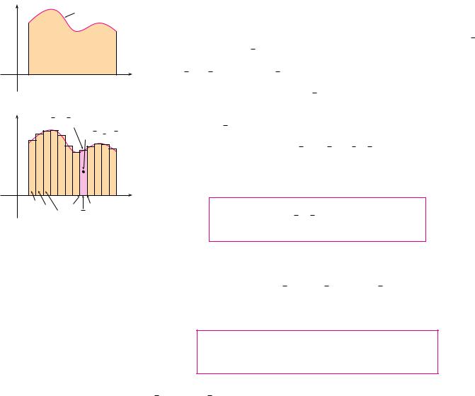
In a similar fashion we compute the moment of Ri about the x-axis as the product of its mass and the distance from Ci to the x-axis:
Mx Ri f xi x 12 f xi
Again we add these moments and take the limit to x-axis:
|
n |
|
|
|
|
|
Mx lim |
|
1 |
f |
|
i 2 |
x |
x |
||||||
n l |
2 |
|
|
|
|
|
|
i 1 |
|
|
|
|
|
12 f xi 2 x
obtain the moment of about the
b |
|
ya 21 |
f x 2 dx |
Just as for systems of particles, the center of mass of the plate is defined so that mx My and my Mx. But the mass of the plate is the product of its density and its area:
|
|
|
|
|
|
|
|
b |
|
|
|
|
|
|
|
|
|
|
|
m |
A ya |
f x dx |
|
|
|||||||
and so |
|
|
|
|
|
|
|
|
|
|
|
|
|
||
|
|
|
|
|
b |
|
|
|
|
|
b |
|
|
|
|
|
|
|
My |
|
ya |
x f x dx |
|
|
ya |
x f x dx |
|||||
|
x |
|
|
|
|
|
|
|
|||||||
|
m |
b |
|
b |
|
|
|||||||||
|
|
|
|
|
|
|
|
|
|
||||||
|
|
|
|
|
ya |
f |
x dx |
|
|
ya |
f x dx |
||||
|
|
|
|
|
b |
|
|
|
|
|
|
|
b |
|
|
|
|
|
Mx |
|
ya 21 f x 2 dx |
|
|
|
|
ya 21 |
f x 2 dx |
||||
|
y |
|
|
|
|
|
|
||||||||
|
m |
|
b |
|
|
|
|
b |
|||||||
|
|
|
|
|
|
|
|
|
|
|
|||||
|
|
|
|
|
ya |
f x dx |
|
|
|
|
ya |
f x dx |
|||
Notice the cancellation of the ’s. The location of the center of mass is independent of the density.
y
y=œ„„„„„r@-≈
4r  ”0, 3π’
_r |
0 |
r |
x |
FIGURE 11
y
y=cos x
”π2 -1, π8’
0 |
π |
x |
|
2 |
|
FIGURE 12
SECTION 8.3 APPLICATIONS TO PHYSICS AND ENGINEERING |||| 545
In summary, the center of mass of the plate (or the centroid of ) is located at the pointx, y , where
|
|
|
|
1 |
b |
|
|
1 |
b |
|
8 |
|
x |
|
|
ya x f x dx |
y |
|
|
ya 21 |
f x 2 dx |
A |
A |
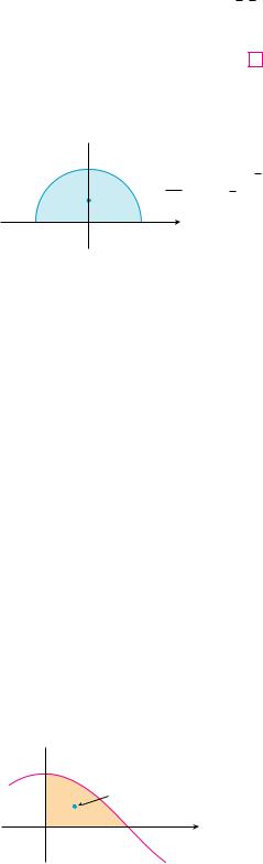
EXAMPLE 4 Find the center of mass of a semicircular plate of radius r.
SOLUTION In order to use (8) we place the semicircle as in Figure 11 so that
f x sr 2 x 2 and a r, b r. Here there is no need to use the formula to calculate x because, by the symmetry principle, the center of mass must lie on the y-axis, so x 0. The area of the semicircle is A 12 r 2, so
|
|
|
|
|
1 |
yr r 21 f x 2 dx |
|
|
|
|
|
|
|
|||||||||||||||
|
|
|
y |
|
|
|
|
|
|
|
||||||||||||||||||
|
|
|
A |
|
|
|
|
|
|
|
||||||||||||||||||
|
|
|
|
|
|
|
|
|
|
|
1 |
|
|
|
|
r |
|
|
|
|
|
|
|
|
|
|
|
|
|
|
|
|
|
|
|
|
|
21 |
y r |
(sr 2 x 2 )2 dx |
|
|
|
||||||||||||||
|
|
|
|
|
21 |
r 2 |
|
|
|
|||||||||||||||||||
|
|
|
|
|
|
|
|
|
|
|
2 |
|
|
|
|
|
|
|
|
|
|
|
2 |
|
|
x 3 |
r |
|
|
|
|
|
|
|
|
|
|
|
|
|
|
|
r |
|
|
|
|
|
|
|
r |
|
0 |
||||
|
|
|
|
|
|
|
|
|
|
y0 r 2 x 2 dx |
|
2x |
|
|||||||||||||||
|
|
|
|
|
r 2 |
|
r 2 |
3 |
||||||||||||||||||||
|
|
|
|
|
|
|
|
|
2 |
|
|
2r 3 |
|
|
4r |
|
|
|
|
|
|
|
|
|||||
|
|
|
|
|
|
r 2 |
|
|
|
3 |
|
3 |
|
|
|
|
|
|
|
|||||||||
The center of mass is located at the point 0, 4r 3 . |
|
|
M |
|||||||||||||||||||||||||
EXAMPLE 5 Find the centroid of the region bounded by the curves y cos x, y 0, |
||||||||||||||||||||||||||||
x 0, and x 2. |
|
|
|
|
|
|
|
|
|
|
|
|
|
|
|
|
|
|
|
|
|
|
|
|
|
|||
SOLUTION The area of the region is |
|
|
|
|
|
|
|
|
|
|
|
|
||||||||||||||||
|
|
|
|
|
|
|
|
|
|
|
|
|
|
|
|
2 |
|
|
|
|
|
|
|
2 |
|
|
|
|
|
|
|
|
|
|
|
|
|
|
|
A y0 |
cos x dx sin x]0 |
1 |
|
||||||||||||||
so Formulas 8 give |
|
|
|
|
|
|
|
|
|
|
|
|
|
|
|
|
|
|
|
|
|
|
|
|
|
|||
|
|
|
|
1 |
|
|
|
2 |
|
|
|
|
|
|
|
|
2 |
|
|
|
|
|
|
|
||||
|
x |
|
|
|
y0 |
|
|
x f x dx y0 |
x cos x dx |
|
|
|
||||||||||||||||
|
|
A |
|
|
|
|
||||||||||||||||||||||
|
|
|
|
|
|
|
|
|
|
|
|
2 |
|
2 |
|
|
|
|
|
|
|
|||||||
|
|
x sin x]0 |
|
|
|
y0 |
|
sin x dx |
(by integration by parts) |
|||||||||||||||||||
|
|
|
|
|
1 |
|
|
|
|
|
|
|
|
|
|
|
|
|
|
|
|
|||||||
|
|
|
|
|
|
|
|
|
|
|
|
|
|
|
|
|
|
|
|
|
|
|||||||
|
|
2 |
|
|
|
|
|
|
|
|
|
|
|
|
|
|
|
|
|
|
||||||||
|
|
|
|
|
|
|
|
|
|
|
|
|
|
|
|
|
|
|
|
|
|
|
|
|
|
|
||
|
|
|
|
1 |
|
|
|
2 |
|
|
|
|
|
|
|
|
|
2 |
|
|
|
|
|
|||||
|
y |
|
|
|
y0 |
|
21 |
f x 2 |
dx 21 |
y0 |
cos2x dx |
|
||||||||||||||||
|
|
A |
|
|
||||||||||||||||||||||||
|
|
|
|
|
|
|
2 |
|
|
|
|
|
|
|
|
|
|
|
|
|
|
|
2 |
|
||||
|
|
|
41 y0 |
|
|
|
1 |
cos 2x dx 41 [x 21 sin 2x]0 |
|
|||||||||||||||||||
|
|
|
|
|
|
|
|
|
|
|
|
|
|
|
|
|
|
|
|
|
|
|
|
|
|
|||
|
|
|
|
|
|
|
|
|
|
|
|
|
|
|
|
|
|
|
|
|
|
|
|
|
|
|
||
8 |
|
|
|
|
|
|
|
|
|
|
|
|
|
|
|
|
|
|
|
|
|
|
|
|||||
|
|
|
|
|
|
|
|
|
|
|
|
|
|
|
|
|
|
|
|
|
|
|
|
|
|
|
||
The centroid is (21 1, 81 ) and is shown in Figure 12. |
|
|
M |
|||||||||||||||||||||||||

546 |||| CHAPTER 8 FURTHER APPLICATIONS OF INTEGRATION
y |
Ci |
”xi |
1 f(xi) +g(xi) ’ |
2
y=ƒ
y©
0 |
a |
|
b |
x |
|
i
FIGURE 13
If the region lies between two curves y f x and y t x , where f x t x , as illustrated in Figure 13, then the same sort of argument that led to Formulas 8 can be used to show that the centroid of is x, y , where
|
|
|
|
1 |
b |
|
|
|
9 |
|
x |
|
|
ya |
x f x t x dx |
|
|
A |
|
|||||||
|
|
|
|
1 |
b |
|
|
|
|
|
y |
|
|
ya |
21 |
f x 2 t x 2 |
dx |
|
|
A |
||||||
|
|
|
|
|
|
|
|
|
(See Exercise 47.)
y
 (1,1)
(1,1)
y=x

 ”21, 25’
  y=≈
y=≈
0x
FIGURE 14
EXAMPLE 6 Find the centroid of the region bounded by the line y x and the parabola y x 2.
SOLUTION The region is sketched in Figure 14. We take f x x, t x x 2, a 0, and b 1 in Formulas 9. First we note that the area of the region is
|
|
|
|
|
|
|
|
|
|
|
|
|
|
|
|
x 2 |
|
|
|
|
x 3 |
1 |
|
1 |
|
|||||
|
|
|
|
|
|
|
|
|
1 |
|
|
|
|
|
|
|
|
|
|
0 |
|
|||||||||
|
|
|
|
|
|
|
A y0 x |
x 2 dx |
|
|
|
|
|
|
|
|
|
|||||||||||||
|
|
|
|
|
|
|
|
2 |
|
|
3 |
6 |
|
|||||||||||||||||
Therefore |
|
|
|
|
|
|
|
|
|
|
|
|
|
|
|
|
|
|
|
|
|
|
|
|
|
|
|
|
||
|
|
|
1 |
1 x f x t x dx |
1 |
|
|
|
1 x x x 2 dx |
|||||||||||||||||||||
|
x |
|
||||||||||||||||||||||||||||
|
|
1 |
|
|||||||||||||||||||||||||||
|
|
|
|
A y0 |
|
|
|
|
|
|
|
|
6 |
|
|
y0 |
|
|
|
|
|
|
|
|
||||||
|
|
|
|
|
1 |
|
|
|
|
|
|
x 3 |
|
|
|
|
|
x 4 |
1 |
1 |
|
|
|
|||||||
|
|
|
|
|
|
|
|
|
|
|
|
|
|
|
|
|
|
|
|
|
|
|||||||||
|
|
|
6 y0 x 2 x 3 |
dx 6 |
|
|
|
|
|
|
|
|
0 |
|
|
|
|
|||||||||||||
|
|
3 |
|
4 |
|
|
2 |
|
|
|
||||||||||||||||||||
|
|
|
1 |
1 |
21 f x 2 t x 2 dx |
1 |
|
1 21 x 2 x 4 dx |
||||||||||||||||||||||
|
y |
|||||||||||||||||||||||||||||
|
|
1 |
||||||||||||||||||||||||||||
|
|
|
|
A y0 |
|
5 0 |
|
|
|
|
|
|
|
|
|
|
|
|
6 y0 |
|
|
|
||||||||
|
|
|
|
|
3 |
|
|
5 |
|
|
|
|
|
|
|
|
|
|
|
|
|
|
|
|
|
|
||||
|
|
|
|
|
|
|
x 3 |
|
x 5 |
1 |
|
2 |
|
|
|
|
|
|
|
|
|
|
|
|
|
|
|
|
|
|
|
|
|
3 |
|
|
|
|
|
|
|
|
|
|
|
|
|
|
|
|
|
|
|
|
|
|
|
|
|
|
|
The centroid is (21 , 52 ). |
|
|
|
|
|
|
|
|
|
|
|
|
|
|
|
|
|
|
|
|
|
|
|
|
|
M |
||||
N This theorem is named after the Greek mathematician Pappus of Alexandria, who lived in the fourth century AD.
We end this section by showing a surprising connection between centroids and volumes of revolution.
THEOREM OF PAPPUS Let be a plane region that lies entirely on one side of a line l in the plane. If is rotated about l, then the volume of the resulting solid is the product of the area A of and the distance d traveled by the centroid of .
PROOF We give the proof for the special case in which the region lies between y f x and y t x as in Figure 13 and the line l is the y-axis. Using the method of cylindrical shells

SECTION 8.3 APPLICATIONS TO PHYSICS AND ENGINEERING |||| 547
(see Section 6.3), we have
V yb 2 x f x t x dx
a
|
|
|
|
b |
|
||
|
|
2 ya x f x t x dx |
|||||
|
|
2 |
|
|
(by Formulas 9) |
||
|
|
xA |
|||||
|
|
2 |
|
|
|
A Ad |
|
|
|
x |
|||||
where d 2 |
|
is the distance traveled by the centroid during one rotation about the |
|||||
x |
|||||||
y-axis. |
M |
||||||
V EXAMPLE 7 A torus is formed by rotating a circle of radius r about a line in the plane of the circle that is a distance R r from the center of the circle. Find the volume of the torus.
SOLUTION The circle has area A r 2. By the symmetry principle, its centroid is its center and so the distance traveled by the centroid during a rotation is d 2 R. Therefore, by the Theorem of Pappus, the volume of the torus is
V Ad 2
R
r 2 2
2r 2R
M
The method of Example 7 should be compared with the method of Exercise 63 in
Section 6.2.
8.3EXERCISES
1. An aquarium 5 ft long, 2 ft wide, and 3 ft deep is full of |
5. |
6 m |
6. |
|
|
water. Find (a) the hydrostatic pressure on the bottom of the |
|
|
1 m |
|
|
aquarium, (b) the hydrostatic force on the bottom, and (c) the |
|
|
|
|
|
hydrostatic force on one end of the aquarium. |
|
|
|
|
|
2. A tank is 8 m long, 4 m wide, 2 m high, and contains kerosene |
|
|
|
|
|
|
|
|
|
|
|
with density 820 kg m3 to a depth of 1.5 m. Find (a) the hydro- |
|
|
|
|
|
static pressure on the bottom of the tank, (b) the hydrostatic |
|
|
|
|
|
force on the bottom, and (c) the hydrostatic force on one end |
7. |
2 m |
8. |
4 m |
|
of the tank. |
|
|
|
|
1 m |
|
|
|
|
|
|
3–11 A vertical plate is submerged (or partially submerged) in water and has the indicated shape. Explain how to approximate the hydrostatic force against one side of the plate by a Riemann sum. Then express the force as an integral and evaluate it.
3.  4.
4.
9. |
|
|
10. |
|||
|
||||||
|
|
|
|
|
|
|

548 |||| CHAPTER 8 FURTHER APPLICATIONS OF INTEGRATION
11.2a
12.A large tank is designed with ends in the shape of the region between the curves y 12 x 2 and y 12, measured in feet. Find the hydrostatic force on one end of the tank if it is filled
to a depth of 8 ft with gasoline. (Assume the gasoline’s density is 42.0 lb ft3.)
13.A trough is filled with a liquid of density 840 kg m3 . The ends of the trough are equilateral triangles with sides 8 m long and vertex at the bottom. Find the hydrostatic force on one end of the trough.
14.A vertical dam has a semicircular gate as shown in the figure. Find the hydrostatic force against the gate.
2 m
water level
12 m
19.A vertical, irregularly shaped plate is submerged in water. The table shows measurements of its width, taken at the indicated depths. Use Simpson’s Rule to estimate the force of the water against the plate.
Depth (m) |
2.0 |
2.5 |
3.0 |
3.5 |
4.0 |
4.5 |
5.0 |
|
|
|
|
|
|
|
|
Plate width (m) |
0 |
0.8 |
1.7 |
2.4 |
2.9 |
3.3 |
3.6 |
|
|
|
|
|
|
|
|
20. (a) Use the formula of Exercise 18 to show that
F tx A
where x is the x-coordinate of the centroid of the plate and A is its area. This equation shows that the hydrostatic force against a vertical plane region is the same as if the region were horizontal at the depth of the centroid of the region.
(b)Use the result of part (a) to give another solution to Exercise 10.
21–22 Point-masses mi are located on the x-axis as shown. Find the moment M of the system about the origin and the center of mass x.
m¡=40 m™=30
21.
0 |
2 |
5 |
x |
4m
15.A cube with 20-cm-long sides is sitting on the bottom of an aquarium in which the water is one meter deep. Estimate the hydrostatic force on (a) the top of the cube and (b) one of the sides of the cube.
16.A dam is inclined at an angle of 30 from the vertical and has the shape of an isosceles trapezoid 100 ft wide at the top and 50 ft wide at the bottom and with a slant height of 70 ft. Find the hydrostatic force on the dam when it is full of water.
17.A swimming pool is 20 ft wide and 40 ft long and its bottom is an inclined plane, the shallow end having a depth of 3 ft and the deep end, 9 ft. If the pool is full of water, estimate the hydrostatic force on (a) the shallow end, (b) the deep end,
(c)one of the sides, and (d) the bottom of the pool.
18.Suppose that a plate is immersed vertically in a fluid with
density and the width of the plate is w x at a depth of x meters beneath the surface of the fluid. If the top of the plate is at depth a and the bottom is at depth b, show that the hydrostatic force on one side of the plate is
F yb tx w x dx
m¡=25 m™=20 m£=10
22.
_2 |
0 |
3 |
7 |
x |
|
|
|
|
|
23–24 The masses mi are located at the points Pi. Find the moments Mx and My and the center of mass of the system.
23.m1 6, m2 5, m3 10; P1 1, 5 , P2 3, 2 , P3 2, 1
24.m1 6, m2 5, m3 1, m4 4;
P1 1, 2 , P2 3, 4 , P3 3, 7 , P4 6, 1
25–28 Sketch the region bounded by the curves, and visually estimate the location of the centroid. Then find the exact coordinates of the centroid.
25. |
y 4 x 2, |
y 0 |
|
||
26. |
3x 2y 6, |
y 0, x 0 |
|||
27. |
y e x, |
y 0, |
x 0, |
x 1 |
|
28. |
y 1 x, |
y 0, |
x 1, |
x 2 |
|
a

SECTION 8.3 APPLICATIONS TO PHYSICS AND ENGINEERING |||| 549
29–33 Find the centroid of the region bounded by the given curves.
29. |
y x 2, |
x y 2 |
|
|
30. |
y x 2, |
y x 2 |
|
|
31. |
y sin x, |
y cos x, |
x 0, x 4 |
|
32. |
y x 3, |
x y 2, |
y 0 |
|
33. |
x 5 y 2, |
x 0 |
|
|
|
|
|
|
|
34 –35 Calculate the moments Mx and My and the center of mass of a lamina with the given density and shape.
40 – 41 Find the centroid of the region shown, not by integration, but by locating the centroids of the rectangles and triangles (from Exercise 39) and using additivity of moments.
40. |
|
y |
41. |
y |
||||
|
|
3 |
|
|
|
|
|
2 |
|
|
2 |
|
|
|
|
|
1 |
|
|
1 |
|
|
|
|
|
|
|
|
|
|
|
|
|
|
|
|
0 |
|
|
_2 |
_1 |
0 |
1 |
2 |
x |
_2 |
1 |
3 |
x |
|
_1 |
|
|
|
|
|
|
|
|
|
|
|
|
|
34. |
3 |
|
|
35. |
10 |
|||||
|
|
y |
|
|
|
|
y |
|
(4,3) |
|
|
1 |
|
|
|
|
|
|
|||
|
|
|
|
|
|
|
|
|
||
|
|
|
|
|
|
|
|
|
|
|
|
0 |
|
1 x |
|
|
|
|
|
||
|
0 |
|
x |
|||||||
|
_1 |
|
|
|
|
|
|
|
|
|
|
|
|
|
|
|
|
|
|
|
|
|
|
|
|
|
|
|
|
|
|
|
36.Use Simpson’s Rule to estimate the centroid of the region shown.
y
4
2
0 |
2 |
4 |
6 |
8 x |
;37. Find the centroid of the region bounded by the curves y 2x and y x 2, 0 x 2, to three decimal places. Sketch
the region and plot the centroid to see if your answer is reasonable.
;38. Use a graph to find approximate x-coordinates of the points of intersection of the curves y x ln x and y x 3 x. Then find (approximately) the centroid of the region bounded by these curves.
39.Prove that the centroid of any triangle is located at the point
of intersection of the medians. [Hints: Place the axes so that the vertices are a, 0 , 0, b , and c, 0 . Recall that a median is a line segment from a vertex to the midpoint of the opposite side. Recall also that the medians intersect at a point twothirds of the way from each vertex (along the median) to the opposite side.]
42.A rectangle R with sides a and b is divided into two parts R1 and R2 by an arc of a parabola that has its vertex at one corner of R and passes through the opposite corner. Find the centroids of both R1 and R2.
y |
|
|
|
R™ |
b |
|
|
|
|
|
R¡ |
0 |
a |
x |
43.If x is the x-coordinate of the centroid of the region that lies under the graph of a continuous function f, where a x b, show that
yb cx d f x dx cx d yb f x dx
a |
a |
44 – 46 Use the Theorem of Pappus to find the volume of the given solid.
44. A sphere of radius r (Use Example 4.)
45.A cone with height h and base radius r
46.The solid obtained by rotating the triangle with vertices2, 3 , 2, 5 , and 5, 4 about the x-axis
47.Prove Formulas 9.
48.Let be the region that lies between the curves y x m and y x n, 0 x 1, where m and n are integers with 0 n m.
(a)Sketch the region .
(b)Find the coordinates of the centroid of .
(c)Try to find values of m and n such that the centroid lies outside .