

Книги по МРТ КТ на английском языке / Thomas R., Connelly J., Burke C. - 100 cases in radiology - 2012
.pdfThis page intentionally left blank
CASE 5: A MECHANICAL FALL IN AN ELDERLY PATIENT
History
An 81-year-old woman is bought into the accident and emergency department by ambulance from a local nursing home. As a long-term resident of the home she is an active participant in daily activities, and is usually self-caring and independent. Yesterday evening, she sustained a witnessed mechanical fall, tripping over the walking stick of another resident. Despite a small graze to the right side of the head, there was no loss of consciousness and the patient reassured care home staff that she was fine. An incident report was filed. During the night the patient took paracetamol for pain control of a headache but no further action was taken.
In the morning, she complained of continued headache and the care staff noted a general listlessness and drowsiness. During the course of the day this progressed, and the patient was found slumped in her chair before lunch, rousable only to strong verbal commands. Staff were worried and called an ambulance.
Examination
On inspection the patient had a superficial graze to the right side of her forehead. Her Glasgow Coma Scale (GCS) was 11 (motor 5, eyes 3, speech 3). She was apyrexial, pulse 76 regular, normotensive with a normal cardiovascular examination. There was no focal neurological deficit, and both pupils were equal and reactive. An unenhanced computed tomography (CT) scan was performed (Figure 5.1).
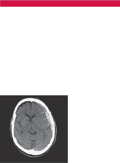
Figure 5.1 Unenhanced CT scan.
Questions
•What does the CT scan demonstrate?
•What is the diagnosis and treatment?
13
ANSWER 5
This is a single unenhanced image from a cranial CT scan at the level of the basal ganglia. There is an area of asymmetry between the inner table of the skull and the brain in the left cerebral hemisphere. This is more dense than adjacent brain parenchyma but not as dense as the calcified bones of the skull. It conforms to the skull in a concave shape and is predominantly homogeneous in appearance. The adjacent sulci are effaced, as they are not traceable to the brain surface compared to the contralateral side. There is also slight effacement of the left lateral ventricle with some mild midline shift to the right. The brain parenchyma demonstrates preserved grey/white matter differentiation, and there is some generalized cerebral atrophy, demonstrated by increased sulcal spaces seen in the normal right cerebral hemisphere. These findings are in keeping with a subdural haemorrhage with mass effect.
Subdural haemorrhage is defined as a collection of blood in the space between pia mater and dura mater of the leptomeninges.
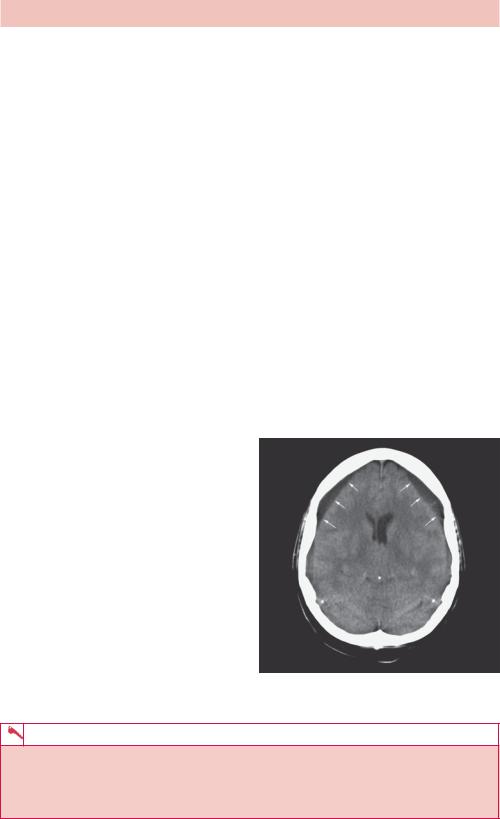
Laceration of the veins between the two inner layers of the meninges causes blood to accumulate in the subdural space. Although there is an association with direct head trauma and penetrating injury, subdural haematomas are most commonly seen within the elderly population. The brain atrophies with age and becomes more mobile within the skull. The bridging cortical veins are stretched, increasing the risk of both spontaneous rupture and disruption after trivial head injury. Blood is free to track along the surface of the brain within the subdural space and is limited only by the falx and tentorium cerebellum. Cranial CT demonstrates a concave haematoma that, unlike an extradural haemorrhage, crosses suture lines within the skull. The haematoma can have a varied attenuation pattern depending on whether it is an acute, subacute or chronic subdural haemorrhage. For example, Figure 5.2 demonstrates bilateral chronic subdural haemorrhages. In some cases where there is rebleeding, layering of
old and fresh blood can be seen, demonstrating an acute-on-chronic picture.
These types of intracranial bleeds tend to be venous in aetiology and blood accumulates slowly in the subdural space. Treatment depends on the neurological deficit caused by the haemorrhage. Patients commonly present with headache, sleepiness and personality change, but if the bleed is large, the conscious level can fluctuate. Signs and symptoms of raised intracranial pressure can occur late and should alert clinicians to the need of urgent evacuation and decompression via a burr hole in a specialist neurosurgical centre. Patients can make a full recovery.
Figure 5.2 CT scan showing bilateral chronic subdural haemorrhages.
KEY POINTS
•In a subdural haemorrhage, blood collects between the pia and dura mater.
•Subdural haemorrhages are more common in the elderly population due to cerebral atrophy.
•Computed tomography demonstrates a concave haematoma unlimited by cranial sutures.
14
CASE 6: RIGHT UPPER ABDOMINAL PAIN
History
A 45-year-old woman presents to the accident and emergency department complaining of continuous right upper quadrant pain. This has been worsening over the last 12 hours. Previously the patient has had intermittent pain in the same area lasting up to a few hours after eating. She had tried some antacids with no benefit. There has been no vomiting. She complains of irregular bowel pattern, predominantly loose, smelly and rather pallid stool for some months. There is no significant past history and she does not take regular medication.
Examination
The woman appears well but in discomfort with normal observations. The cardiovascular and respiratory examination is normal. The abdomen is soft but focally tender over the right liver edge. The liver is not enlarged. There is no renal angle tenderness.
You arrange tests including an ultrasound of the abdomen (Figure 6.1).
(a) |
(b) |
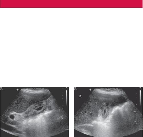
Figure 6.1 Ultrasound views of the liver and gallbladder in longitudinal (a) and transverse
(b) planes.
Questions
•What differential diagnoses are you considering?
•What does the ultrasound show?
•Is ultrasound the best investigation to start with?
15
ANSWER 6
The stool appearance and Murphy’s point tenderness point to gallbladder inflammation although the differential includes liver pathology, pancreatitis, gastric or duodenal ulcer, renal obstruction or infection.
The ultrasound shows a partially filled gallbladder with a thickened irregular layered oedematous wall (>3 mm). The gallbladder contains two small stones that reflect virtually all of the beam, giving a shadow appearance behind the stone. A stone is seen in the gallbladder neck and part of the ultrasound examination is to roll the patient onto the right side to see if the stones are mobile. In this case the stone is fixed at the gallbladder neck. These are the appearances of acute obstructive cholecystitis.
For suspected gallbladder or biliary abnormalities, an ultrasound is a good starting investigation. Ultrasound has a very high sensitivity for gallstones whereas at least 20 per cent of gallstones are not seen on computed tomography (CT). Biliary dilatation is also easily seen on ultrasound, appearing as an extra tube running alongside the intrahepatic portal veins (double-barrel sign) or as an extrahepatic dilated common bile duct. Sometimes the cause of obstruction is seen, although the proximity of gas in the stomach, duodenum and hepatic flexure of the colon can often obscure extrahepatic causes. An abdominal radiograph is often included in the work up and is helpful to look for other causes such as renal stones causing colic. Only 30 per cent of gallstones contain enough calcium to be radio-opaque and visible on the abdominal radiograph.
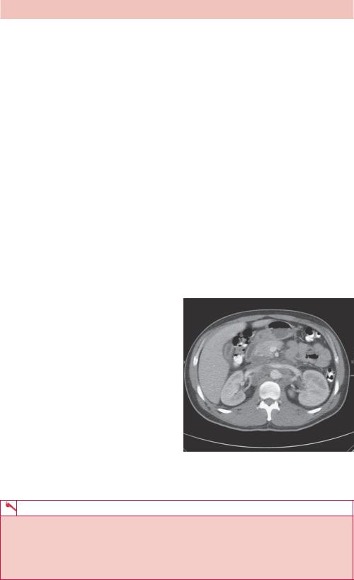
The signs of cholecystitis are also seen frequently on CT that may be done if there is uncertainty as to the diagnosis (Figure 6.2).
Cholecystitis results from obstruction of the cystic duct and in about 90 per cent of cases this is caused by a calculus. In 80 per cent these are cholesterol based, 20 per cent are pigment based. A few cases are caused by sludge that is a fine calcified sediment that forms if the bile becomes very concentrated. The remainder are acalculous cholecystitis, which has all the inflammatory signs without stones and tends to occur in systemic illness, biliary stasis and local or systemic ischaemia. Rarely, gas within the gallbladder or biliary tree is seen if there is added infection.
Figure 6.2 Axial contrast CT scan through the gallbladder showing fluid around the gallbladder.
KEY POINTS
•Ultrasound is a good test for gallbladder and biliary problems.
•Murphy’s sign – focal tenderness over the gallbladder – is frequently elicited by the pressure of the ultrasound probe.
•Look on the ultrasound for gallstones, gallbladder wall thickening and oedema as signs of cholecystitis and gas as a sign of infection.
16
CASE 7: HEARTBURN, EPIGASTRIC PAIN AND A COUGH
History
A 67-year-old man presents to his general practitioner (GP) with a cough. The man was well known to the doctor as he had been a regular attendee over the course of the previous 12 months with recurrent chest infections. His background included longstanding symptoms of heartburn, dyspepsia and epigastric pain, for which he was prescribed a regular proton pump inhibitor (with some relief). He took no other medications, however, and lived at home with his wife.
Examination
No abnormalities were found on examination of the chest. His respiratory rate was 18 breaths per min with equal and good air entry bilaterally, vesicular breath sounds with no added sounds. He was referred for a chest radiograph (Figure 7.1) but on the basis of the radiograph the reporting radiologist suggested an upper gastrointestinal (GI) contrast swallow examination (Figure 7.2). One day following the barium swallow examination the patient presented acutely in the accident and emergency department with symptoms of epigastric pain, and a computed tomography (CT) scan was performed (Figure 7.3).
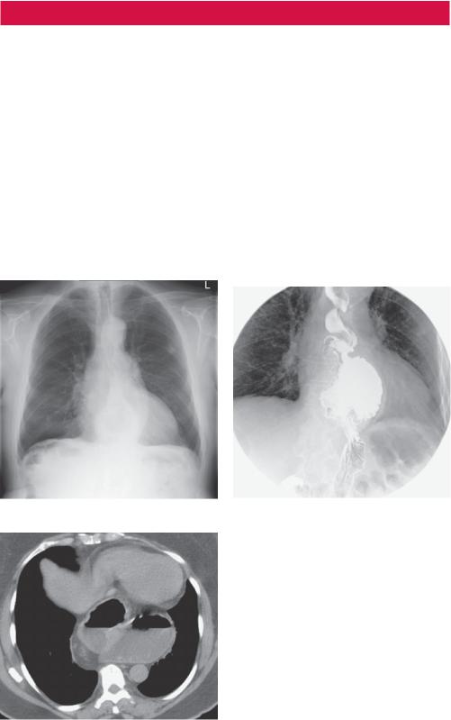
Figure 7.1 Chest radiograph. |
Figure 7.2 Upper GI contrast swallow exam. |
Questions
• What does the plain chest radiograph demonstrate (Figure 7.1)?
• Why would the radiologist suggest a barium swallow examination?
• What do the barium swallow spot image (Figure 7.2) and axial enhanced CT image (Figure 7.3) show?
Figure 7.3 CT scan.
17
ANSWER 7
Spot images taken from a barium swallow examination confirm the presence of a sliding hiatus hernia (Figure 7.2). The axial enhanced CT image (Figure 7.3) again demonstrates a large sliding hiatus hernia extending into the thorax. The chest radiograph shows a gas-filled viscus behind the heart shadow consistent with a hiatus hernia. An upper GI contrast examination would confirm the presence of a hiatus hernia and any associated gastro-oesophageal reflux to account for the patient’s symptoms.
A hiatus hernia occurs when part of the stomach protrudes into the thoracic cavity through the oesophageal hiatus of the diaphragm. Hiatus hernias are classified either as sliding hernias (where the gastro-oesophageal junction moves above the diaphragm together with part of the stomach) or para-oesophageal or ‘rolling’ hiatus hernias (where part of the stomach herniates through the oesophageal hiatus and lies beside the oesophagus without movement of the gastro-oesophageal junction). Approximately 95 per cent of hiatus hernias are sliding and the remaining 5 per cent are para-oesophageal.
Plain chest radiographs (as in Figure 7.1) may demonstrate a retro-cardiac mass with or without an air–fluid level. When air is seen within the hernia, the stomach air bubble found below the diaphragm tends to be absent. The hernia is usually positioned to the left of the spine, however larger hernias (particularly when incarcerated) may extend beyond the cardiac confines and even mimic cardiomegaly.
An upper GI barium series (as in Figure 7.2) is the preferred examination in the investigation of hiatus hernia and its sequelae. A single-contrast barium swallow performed with the patient prone is more likely to demonstrate a sliding hiatal hernia than an upright double-contrast examination. The hernia can usually be recognized by the demonstration of mucosal gastric folds. CT scans are useful when more precise cross-sectional anatomic localization is desired.
Most hiatus hernias are actually found incidentally, often being discovered on routine chest radiographs or CT scans performed for unrelated symptoms. When symptomatic, common symptoms include heartburn, dyspepsia or epigastric pain. On occasions, as in this case, the patient may present with recurrent chest infections resulting from aspiration of gastric contents. One sequel of hiatus hernia (particularly the sliding form) is the development of Barrett’s oesophagus, which may present with reflux symptoms or dysphagia.
With a para-oesophageal or rolling hernia, part of the stomach rolls into the thorax often anterior to the esophagus and is frequently irreducible. Therefore this type of hernia is more likely to present acutely because of a volvulus or strangulation. A para-oesophageal hiatal hernia is diagnosed by the position of the gastro-oesophageal junction. The cardia of the stomach and gastro-oesophageal junction usually remain in the normal position below the diaphragmatic hiatus and only the stomach herniates into the thorax adjacent to the normally placed gastro-oesophageal junction. This type of hernia, (unlike the sliding form) is not associated with gastro-oesophageal reflux.
KEY POINTS
•Hiatus hernias are frequently diagnosed incidentally on routine chest radiographs.
•The hernia may be seen as a retro-cardiac mass with or without an air–fluid level.
•An upper GI barium series or barium swallow study is the examination of choice for demonstrating a hiatus hernia, gastro-oesophageal reflux and any associated complications (e.g. Barrett’s oesophagus).
•A para-oesophageal or, rarely, sliding hiatal hernia may present acutely because of a volvulus or strangulation.
18
CASE 8: LINES, CATHETERS AND TUBES ON A RADIOGRAPH
History
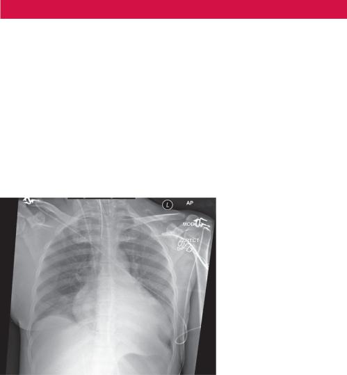
A 59-year-old woman has recently been admitted to the intensive care department. She has chronic renal failure and relies on peritoneal dialysis every night. This morning, while attending her clinic appointment, she complained of a sudden onset of headache and collapsed to the ground, shaking violently. The emergency ‘crash’ team were called immediately and found the patient unresponsive with generalized jerking movements. The senior doctor decided that she should be paralysed, intubated and ventilated for protective measure, and she was then transferred to the intensive care department for further management. The patient was satisfactorily stabilized, and a central line was placed in her right internal jugular vein for the infusion of intravenous medication and to monitor her central venous pressures. A chest radiograph has been performed to confirm correct placement before its use (Figure 8.1), which you have been asked to report.
Figure 8.1 Chest radiograph.
Questions
•What additional lines and tubes does this radiograph demonstrate?
•Are the lines and tubes correctly positioned?
•What other common medical equipment may be seen on a radiograph?
19
ANSWER 8
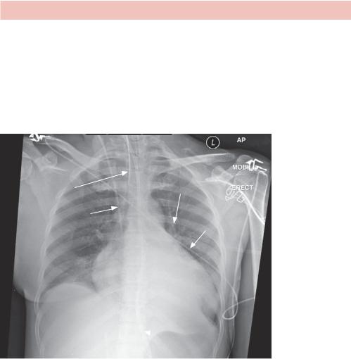
Any radiograph can be complicated by additional shadows from foreign lines or drains. Their presence implies that the patient is unwell, and it is important to not only recognize the type of line and common complications associated with its insertion, but its presence on the film should not be a distraction to reporting pathological change (for example, left lower lobe collapse in Figure 8.2). These types of films are often mobile examinations from intensive care (ITU) patients and can be complicated by rotation, poor inspiratory effort and an anterior–posterior (AP) projection. The commonest lines are discussed below, with chest drains discussed in a separate case; see Case 27.
Nasogastric tube on
patients skin
Endotracheal tube
Right internal jugular |
Cardiac monitoring |
|
wire |
||
central venous catheter |
||
|
 Nasogastric tube as it passed GOJ
Figure 8.2 Chest radiograph with labels.
•Endotracheal (ET) tubes: A patient is intubated for reasons of mechanical ventilation and airway protection usually because they are critically ill or undergoing anaesthesia. Correct placement is critical and an ET tube is recognized on a chest radiograph as a linear opacity projected over the trachea in the midline. Insertion of an ET tube is beyond the scope of this book, but once in the trachea a radiolucent balloon cuff is inflated to maintain stability and a mechanical seal. The tubes are positioned blindly by an airway expert and a chest radiograph is used to confirm its position. Ideally, the tip of an ET tube should be located within the trachea, approximately 1–2 vertebral body heights above the carina. This allows ventilation of both lungs and incorrect placement should be highlighted urgently to the referring clinician. The commonest abnormality is advancement of the ET tube into the right main bronchus preferentially ventilating the right lung only. If not corrected, the patient may be compromised by left lung collapse. An example of an ET tube in the right main bronchus is given in Figure 8.3.
20
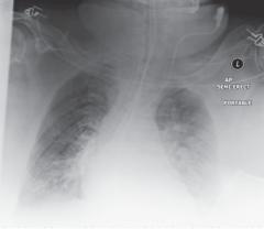
Figure 8.3 Chest radiograph showing ET tube in right main bronchus.
•Nasogastric (NG) tubes: These are placed in patients for numerous reasons, most commonly nutritional. Correlating the position of an NG tube does not necessarily require a chest radiograph. Testing the pH of the aspirate can confirm placement within the stomach, thereby avoiding unnecessary radiation exposure. If this is not possible, a chest radiograph should demonstrate the NG tube as a midline linear opacity extending below the left hemidiaphragm. This confirms its presence in the stomach and not in a main stem bronchus, avoiding the catastrophic infusion of nutritional support into the lungs. The tip of an NG tube is not always seen on the chest radiograph, but should lie within the stomach. It can sometimes migrate into the duodenum with gastric peristalsis and should be partially withdrawn.
•Central lines: Primarily placed in patients for the infusion of intravenous medication, central lines can also avoid the need for peripheral cannulation and risks of thrombophlebitis. A chest radiograph is performed post insertion to confirm tip position and exclude the most serious complication of pneumothorax. A central line is a radioopaque density projected paramedially over the internal jugular or subclavian vessels, and can have a wide variety of appearances depending on the side it is inserted and how many lumens the line contains (Figure 8.4). It may also be tunnelled under the skin in the case of a Hickman line, with the possible addition of a buried metallic port (portacath). Recognizing the type of line is important but not essential. Correct tip positioning is critical for optimal infusion. The tip of a central line should ideally lie at the confluence of the inferior and superior vena cava as blood drains into the right atrium. This is identified on a chest radiograph at a point approximately one vertebral body height below the carina. A short line position carries thrombotic risks, while overenthusiastic advancement into the right atrium can encourage myocardial excitation and atrial ectopics.
•Others: ET tubes are not suitable for patients requiring long-term ventilatory support and often a tracheotomy is inserted just inferior to the cricoid cartilage. Lying in the midline within the superior mediastinum, a tracheotomy tube appears as a radioopaque curvilinear density with a buttressed cuff at the skin surface. Its tip should lie within the trachea above the carina.
Figure 8.4 also shows cardiac monitoring and pacing equipment. The two paddle-shaped radio-densities are adhesive conducting pads, and are used to monitor a patient’s heart rhythm, control the heart rate through electrical pacing and can be used to deliver an electrical cardioversion shock if necessary. They are correctly positioned here along the electrophysiological axis of the heart. Continuous cardiac monitoring is performed by
21