


Extrahepatic Bile Duct

130
3 Extrahepatic Bile Duct
3.1 Normal Anatomy and Variants
#61 Normal Anatomy, Terminology,
and Size
KEY FACTS
●Common hepatic duct: portion of bile duct above the cystic duct and below the bifurcation
●Common bile duct: portion above the papilla and below the cystic duct
!● Normal maximal diameter:
–Simplifying rule: 5 mm for patients up to age 50, plus 1 mm per decade over age 50 (duct walls are composed of elastic fibers; loss of elasticity may occur with age)
–In fact, a wide range of diameters are encountered in “normal” asympto-
matic patients; diameters up to 10 mm may be observed in individuals under 50 years, even in the absence of disease (Fig. 61)
–A normal bile duct diameter does not rule out (obstructive) disease
–After cholecystectomy, dilatation of the common bile duct occurs; the increase in diameter is usually small (<1 mm), however (Feng and Song 1995)
References
Feng B, Song Q (1995) Does the common bile duct dilate after cholecystectomy? Sonographic evaluation in 234 patients. AJR Am J Roentgenol 165 : 859–861
Lasser RB, Silvis SE, Vennes JA (1978) The normal cholangiogram. Am J Dig Dis 23 : 586–590
Rohrman CA, Baron RL (1989) Biliary complications of pancreatitis. Radiol Clin North Am 27 : 93–104
3 Extrahepatic Bile Duct 131
a |
b |
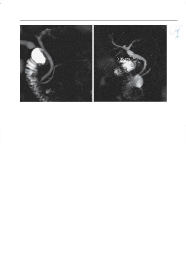
Fig. 61. a Projective image obtained in an asymptomatic patient showing a normal common hepatic and common bile duct. b Projective image obtained
in an asymptomatic 80-year-old patient. Diameters up to 10 mm may be observed in this age group

132 3.1 Normal Anatomy and Variants
#62 Variant Anatomy (1):
Narrow Aspect
of the Pancreatic Segment
KEY FACTS: ANATOMY
●Course of the normal bile duct (Fig. 62a):
–Through the pancreatic parenchyma (± 65%)
–In a groove in the posterior aspect of the pancreatic head (± 25%)
–Posterior to the pancreatic head and totally extrapancreatic (±10%)
●If the distal common bile duct courses through the pancreatic parenchyma, it may be smaller in diameter than the suprapancreatic portion
KEY FACTS: MRI
●Diagnostic clues (Fig. 62):
–Gradual tapering
–Absence of mass lesion
–Intrapancreatic site of the common bile duct on axial images
●Widening of the distalmost part of the common bile duct is sometimes observed (corresponding to the presphincteric segment that is located outside the pancreas)
●Differential diagnosis: e.g., acute or chronic pancreatitis, pancreatic neoplasms
References
Van Hoe L, Mermuys K, Vanhoenacker P (2004) MRCP pitfalls. Abdom Imaging 29 : 360–387
3 Extrahepatic Bile Duct 133
a
b
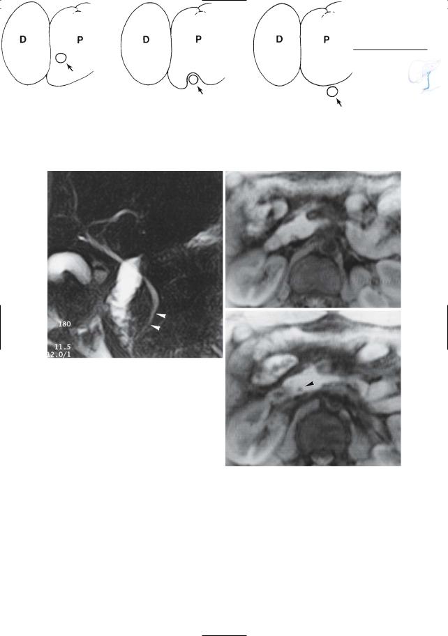
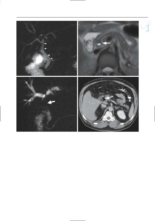
Fig. 62. a Variations in the anatomic relationship of the common bile duct and the head of the pancreas. Left,intrapancreatic course; center,in dorsal groove; right, extrapancreatic. (From Rohrman and Baron 1989, with permission). b–d Projective image showing apparent narrowing of the distal part of the common bile duct (arrowheads). c, d Axial T1weighted images showing the intrapancreatic location of the distalmost portion of the common bile duct (arrowhead in d)
c
d

134 3.1 Normal Anatomy and Variants
#63 Variant Anatomy (2):
Location of the Bifurcation
Related topic: #82 (after cholecystectomy: stricture of the common bile duct)
KEY FACTS
●Right and left main hepatic ducts usually join up just outside the porta hepatis (± 1 cm under the edge of the liver)
●However, the site of union may be much lower:
–In extreme cases, the right and left ducts drain separately into the duodenum
–In individuals with low union or nonunion, the cystic duct drains into the right hepatic duct
●Note: Low bifurcation is clinically significant in that it carries an increased risk for injury during (laparoscopic) cholecystectomy (see Fig. 52a)
References
Taylor AJ,Bohorfoush AG (1997) Normal anatomy of the biliary tree. In: Taylor AJ, Bohorfoush AG (eds) Interpretation of ERCP. Lippincott-Raven, Philadelphia, pp 59–76
3 Extrahepatic Bile Duct 135
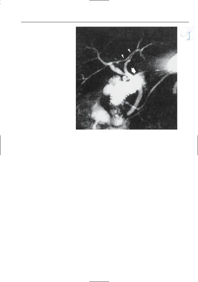
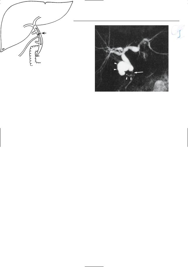
Fig. 63. Projective MR image showing low bifurcation; the cystic duct drains into the bile duct just below the bifurcation (arrow). Also note the right posterior hepatic duct draining into left hepatic duct (arrowheads) and pancreas divisum (see # 140)

136 3.1 Normal Anatomy and Variants
#64 Variant Anatomy (3):
Impression by Blood Vessels
KEY FACTS: ANATOMY
●The common hepatic duct is accompanied by:
–The portal vein (posteriorly)
–The hepatic artery (medially)
–The right hepatic artery and cystic artery (posteriorly)
●An aberrant cystic artery may also cross anterior to hepatic duct
●Blood vessels (usually the right hepatic artery) may cause an impression on the posterior aspect of the common hepatic duct
KEY FACTS: MRI
●MRCP may overestimate vascular impressions or falsely “create” impressions by the following mechanism:
–Bile duct and vessel contained in one section (volume averaging)
–Flow-related intravascular signal void reduces “overall” signal per voxel
–Focally decreased signal intensity of a ductal segment suggests narrowing or external compression (Fig. 64b)
●Diagnostic clues:
–Typical location and shape
–Coronal cross-sectional images show crossing vessel (Fig. 64a)
References
Reuther G, Kiefer B, Tuchman A (1996) Cholangiography before biliary surgery: single-shot MR cholangiography versus intravenous cholangiography. Radiology 198 : 561–566
!
!
3 Extrahepatic Bile Duct 137
a
c
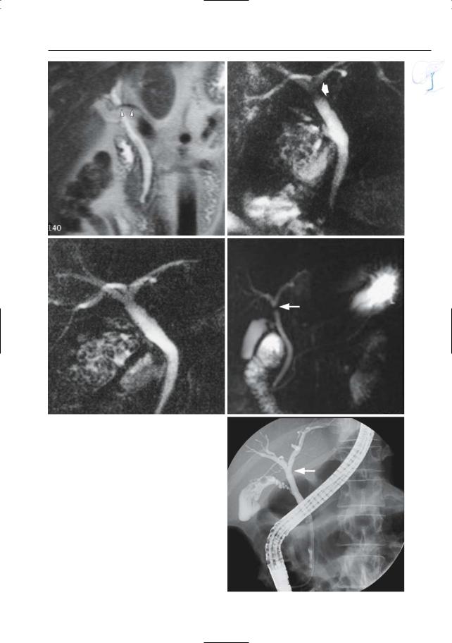
Fig. 64 a–e. a Coronal T2-weighted image showing the right hepatic artery crossing the common hepatic duct (arrowheads). Two projective images consecutively obtained in the same patient. b The first image shows a hypointense band just below the bifurcation (arrow), which could be mistaken for an organic stricture. c The second image shows less artifact. d–e Different patient. Projective image showing a hypodense band just below the bifurcation with shape and location suggestive of a vascular impression (arrow). e ERCP image confirms the absence of a stricture (arrow)
b
d
e
138 3.1 Normal Anatomy and Variants
#65 Postoperative Anatomy:
After Hepatic Transplantation
Related topics: #80, 81 (complications after hepatic transplantation)
KEY FACTS: TECHNIQUE
●Three types of biliary anastomoses exist:
–Choledocho-choledochostomy (Fig. 65) (most common type)
–Choledochojejunal anastomosis
–Choledocho-cholecysto-choledochal anastomosis (least common type)
●The gallbladders are usually removed
●Both cystic duct stumps are usually pre-
served
–Nonobstructive dilation is common:
–Usually occurs in the initial postoperative period
–Generally does not resolve with time
–Mean donor dilation: 0.8 mm (in 15% of patients more than 3 mm)
–Possible mechanisms: low-grade ischemia; postcholecystic reservoir effect; dysfunction of the vaterian sphincter complex (damage to neural
reflex arcs)
●Size mismatch between the donor and the native common bile duct is also common
KEY FACTS: MRI
●Normal variants that may mimic disease (Fig. 65b):
–Size mismatch
–Mild, nonobstructive dilation of donor and/or native extrahepatic duct
●Differential diagnosis with pathologic narrowing:
–Lack of dilation of intrahepatic bile ducts
–Liver function tests
References
Campbell WL, Foster RG, Miller WJ, Lecky JW, Zajko AB, Lee KY (1992) Changes in intrahepatic bile duct caliber in liver transplant patients without evidence of biliary obstruction. AJR Am J Roentgenol 158 : 997–1000
Silvis S, Rohrmann C, Ansel H (eds) (1995) Endoscopic retrograde cholangiopancreatography. Igaku-Shoin, New York, p 289
Zoepf T,Maldonado-Lopez EJ,Hilgard P,et al. (2005) Diagnosis of biliary strictures after liver transplantation: which is the best tool? World J Gastroenterol 11 : 2945–2948
3 Extrahepatic Bile Duct 139
a
Fig. 65. a Choledocho-choledochal anastomosis in hepatic transplantation. The anastomosis is located in between the two cystic duct stumps. Note: The use of a T tube is not universal. (Reprinted with permission from Silvis et al. 1995). b Projective MR image obtained a few days after hepatic transplantation
b
showing marked size mismatch between donor and native common bile duct, as well as between the two cystic duct remnants (arrowheads). Also note apparent narrowing of anastomosis (arrow), most likely related to edema. Clinically and biochemically, there were no signs of biliary obstruction

140 3.1 Normal Anatomy and Variants
#66 Postoperative Anatomy:
After the Whipple Procedure
Related topic: #29 (postoperative anatomy: after hepat(ic)ojejunostomy)
KEY FACTS: TECHNIQUE
●Types:
–Classical Whipple operation: radical pancreaticoduodenectomy with removal of the pancreatic head, associated biliary tree, duodenum, and gastric antrum
–Modified Whipple procedure: the pylorus and first portion of the duodenum are left intact. The advantages of the modified procedure include maintenance of intact gastric reservoir capacity and decreased incidence of jejunal ulceration and bile reflux
●The following anastomoses are made (Fig. 66a):
–Hepaticojejunostomy
–Pancreatojejunostomy
–Duodenojejunostomy
●Indications:
–Resection of tumor located in right hemipancreas
–Diversion of bile system or main pancreatic duct
KEY FACTS: MRI
●The hepatojejunal and pancreatojejunal anastomoses are usually clearly visible (Fig. 66b)
●Criteria for a normal anastomosis: see #29
●Critical elements of technique: administration of oral contrast agent (e.g., tap water) and spasmolytic drug
●Good distention of the jejunal loop enables recognition of the following:
–Normal valvulae conniventes (important to differentiate jejunum from a mass, pseudocyst, etc.)
–Exact location of the anastomosis
References
Schopohl J, Zöckler CE, Draese K (1986) Modified Whipple surgical procedure. Chirurg 57 : 517–521 Taylor AJ, Bohorfoush AG (1997) Interpretation of
ERCP. Lippincott-Raven, Philadelphia, p 298 Trerotola SO, Jones B, Crist DW, Cameron JL (1989)
Pylorus-preserving Whipple pancreaticoduodenectomy: postoperative evaluation. Radiology 171 : 735–738
3 Extrahepatic Bile Duct 141
a |
b |
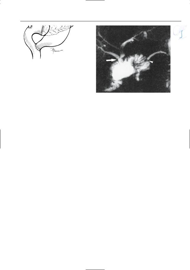
Fig. 66. a Modified Whipple procedure. (Reprinted with permission from Taylor and Bohorfoush 1997). b Projective image showing normal aspect of hepa-
ticojejunal (arrow) and pancreatojejunal (arrowhead) anastomoses

142 3.1 Normal Anatomy and Variants
#67 Aerobilia
Related topic: # 73 (stones in the common bile duct: pitfalls in diagnosis)
KEY FACTS: GENERAL
●Causes:
–ERCP/PTC (most common)
–Biliary surgery
–Bilioenteric fistulas (see # 103)
–Patent papilla (see Fig. 124)
KEY FACTS: MRI
●Signal void (absence of protons)
!● Differentiation from stones:
–Appearance: often more elongated, margins less clear
–Presence of an air–fluid level on axial images (most reliable sign) (Fig. 67)
–Change in shape/location after patient repositioning (ventral versus dorsal decubitus)
●Note: MRI underestimates aerobilia compared to CT; in some patients with large amounts of air, however, susceptibility may mimic bile duct stenoses at projective MRCP (Fig. 67 c, d)
References
Irie H, Honda H, Kuroiwa T et al. (2001) Pitfalls in MR cholangiopancreatographic interpretation. Radiographics 21 : 23–37
Reinhold C, Bret P (1996) MR cholangiopancreatography. Abdom Imaging 21 : 105–116
Van Hoe L, Mermuys K, Vanhoenacker P (2004) MRCP pitfalls. Abdom Imaging 29 : 360–387
3 Extrahepatic Bile Duct 143
a |
b |
c |
d |
Fig. 67 a–d. a Projective image showing multiple uniform rounded areas of signal void in the common bile duct and the common hepatic duct (arrowheads). b Axial T2-weighted HASTE image (TE 60) showing an air–fluid level in the common bile duct (arrow),
diagnostic of intraluminal air. c, d Different patient. Projective image showing a large area of signal loss in the common hepatic duct (arrow). d Axial CT image showing air in the common bile duct (arrow). Extensive aerobilia was the cause of the signal loss at MRI