


XIX
Abbreviations
CBD |
Common Bile Duct |
MRCP |
Magnetic Resonance |
CT |
Computed Tomography |
|
Cholangio-Pancretography |
DD |
Differential Diagnosis |
MRI |
Magnetic Resonance Imaging |
EPI |
Echo Planar Imaging |
PTC |
Percutaneous Transhepatic |
ERCP |
Endoscopic Retrograde Cholan- |
|
Cholangiography |
|
gio-Pancreatography |
RARE |
Rapid Acquisition |
EUS |
Endoscopic Sonography |
|
with Relaxation Enhancement |
FSE |
Fast Spin Echo |
RES |
Reticulo Endothelial System |
GE |
Gradient Echo |
SE |
Spin Echo |
HASTE |
Half-Fourier Single-Shot |
SI |
Signal Intensity |
|
Turbo Spin Echo |
T |
Tesla |
HCC |
Hepatocellular Carcinoma |
TE |
Echo Time |
IV |
Intravenous |
TR |
Repetition Time |
MEN |
Multiple Endocrine Neoplasia |
TSE |
Turbo Spin Echo |
MIP |
Maximum Intensity Projection |
US |
Sonography |
MP |
Magnetization Prepared |
VSC |
Vaterian Sphincter Complex |
MR |
Magnetic Resonance |
|
|
MRA |
Magnetic Resonance |
|
|
|
Angiography |
|
|

1
IIntroduction: Basic Principles
of Magnetic Resonance Imaging
1Magnetic Field, Radio Frequency Pulses, and Resonance
Magnetic resonance imaging (MRI) does not use X-rays to produce images. MRI relies on the fact that hydrogen nuclei (protons) behave like small magnets.When placed in an external magnetic field, the protons align along the direction of the field. In clinical magnetic resonance (MR) systems, the strength of the magnetic field varies between 0.2 and 2 T, which is much higher than the earth’s magnetic field (0.6 ¥ 10– 4 T). The net result of the specific orientation of the billions of protons is a macroscopic magnetization vector that is aligned with the field. The external magnetic field is oriented parallel to the longitudinal body axis of the patient (z-axis).
The alignment of the protons can be perturbed by a pulse of external electromagnetic energy (excitation). This energy pulse is called a radio frequency (RF) pulse. Excitation can only occur if the radio frequency pulse has a frequency similar to the “natural” frequency of the protons themselves. This transfer of energy is called resonance. The angle over which the magnetization vector is tilted away from the z-axis is called the flip angle. In conventional MRI, a 90° flip angle is used and the magnetization vector is tilted from the z- axis to the transverse (xy) plane (Fig. I.1). In technical terms, longitudinal magnetization is changed into transverse magnetization. After perturbation, the spins return to their equilibrium state (Fig. I.1, right). This return to equilibrium is called relaxation.
Fig. I.1. T1 and T2 relaxation in MRI. After an excitation pulse (radio frequency pulse), the magnetization vector (thick arrow) is flipped towards the axial plane. During relaxation, the longitudinal magnetization gradually recovers (T1 relaxation), while the
transverse magnetization gradually disappears (T2 relaxation). The T1 and T2 relaxation times are tissue specific and form the basis of image contrast in MRI

2Introduction: Basic Principles of Magnetic Resonance Imaging
2 T 1- and T 2-Weighted Images
Relaxation is characterized by relaxation times, which are specific for each biological tissue. Two different components of relaxation can be distinguished (Fig. I.1). T1 relaxation reflects the gradual recovery of the longitudinal magnetization (longitudinal relaxation), while T2 relaxation reflects the loss of transverse magnetization (transverse relaxation). Both T1 and T2 relaxation times are tissue-dependent parameters; the differences between relaxation times of various tissues is the source of contrast in MRI.
In order to obtain an MR signal (or echo),the transverse magnetization is measured shortly after the radio frequency pulse. The time interval between the radio frequency pulse and the measurement of the echo is called the echo time (TE). The echo time, together with the repetition time (TR, i.e. the time interval between two consecutive 90° pulses), determines which type of MR image is created. A T1-weighted image is one in which the intensity contrast between any two tissues in an image is due mainly to the T1 relaxation properties of the tissues. Similarly, a T2-weighted image is one in which the intensity contrast between any two tissues is due mainly to their T2 relaxation properties. To produce a T1weighted image,short TE and TR values are used (typical values: TR £ 500 ms; TE £ 20 ms). Use of long TE and TR values results in the creation of a T2-weighted image (typical values: TR >1500 ms; TE > 40 ms). T1and T2-weighted images can be distinguished by considering the signal intensity (SI) of water or water-containing structures (e.g., cerebrospinal fluid): as a general rule, water has a low signal intensity on T1-weighted images (i.e.,it is rendered black), while it has a high signal intensity on T2-weighted images (i.e., it is rendered white).
3Imaging Times in “Classical” Magnetic Resonance Imaging
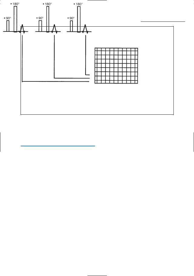
The classical technique for obtaining MR images is called spin echo. In this technique, a 90° radio frequency pulse is followed by a 180° pulse (the purpose of adding a 180° pulse is to avoid signal loss caused by local inhomogeneity in the magnetic field).After each 90° (and 180°) pulse, an echo is measured. Each echo is used to fill a single horizontal line in a raw data matrix called k- space (Fig. I.2). The process is then repeated by applying a second 90° pulse and so on. Once all lines of the raw data matrix have been filled, sufficient information is available to calculate an image.
An important constraint in spin echo MRI is that,in order to allow for recovery of the longitudinal magnetization after a 90° pulse,TR values should be sufficiently long. Because of this, and because many (typically ± 256) consecutive 90° pulses have to be applied to fill all the lines in k-space, spin echo MRI is a rather slow technique that cannot be used for imaging during breathholding. In order to reduce the total examination time, adjacent slices are excited and measured during the spin relaxation of the first slice,i.e.,before the next 90° pulse is applied. This procedure is repeated for the acquisition of all necessary k-space lines. If this technique (known as multislice MRI) is applied, the total examination time (i.e., the time required to examine a predefined number of slices) roughly corresponds to the time required to examine a single slice. Typical acquisition times required to obtain high-quality T1and T2-weighted images of the upper abdomen with spin echo MRI are 2–3 and 8–10 min, respectively.
Introduction: Basic Principles of Magnetic Resonance Imaging |
3 |
Fig. I.2. Data collection in spin echo MRI.One horizontal line of the raw data matrix (k-space) is filled after each 90° excitation pulse. The scan time is determined by the length of the TR (i.e., the time interval between two consecutive 90° pulses), and
by the total number of lines to be filled. Since both TR and the number of 90° pulses should be sufficiently large (typical values: TR 0.5 s; number of 90° pulses, 256) to obtain images with acceptable quality, spin echo MRI is a rather slow technique
4Fast and Ultrafast Magnetic Resonance Imaging
While it was initially believed that rapid MRI would be impossible, several solutions were proposed in the mid-1980s. Two major independent approaches to reduce acquisition times in MRI are (1) the generation of multiple echoes after a single excitation pulse and (2) the replacement of the classical 90° excitation pulse by lower flip angles.
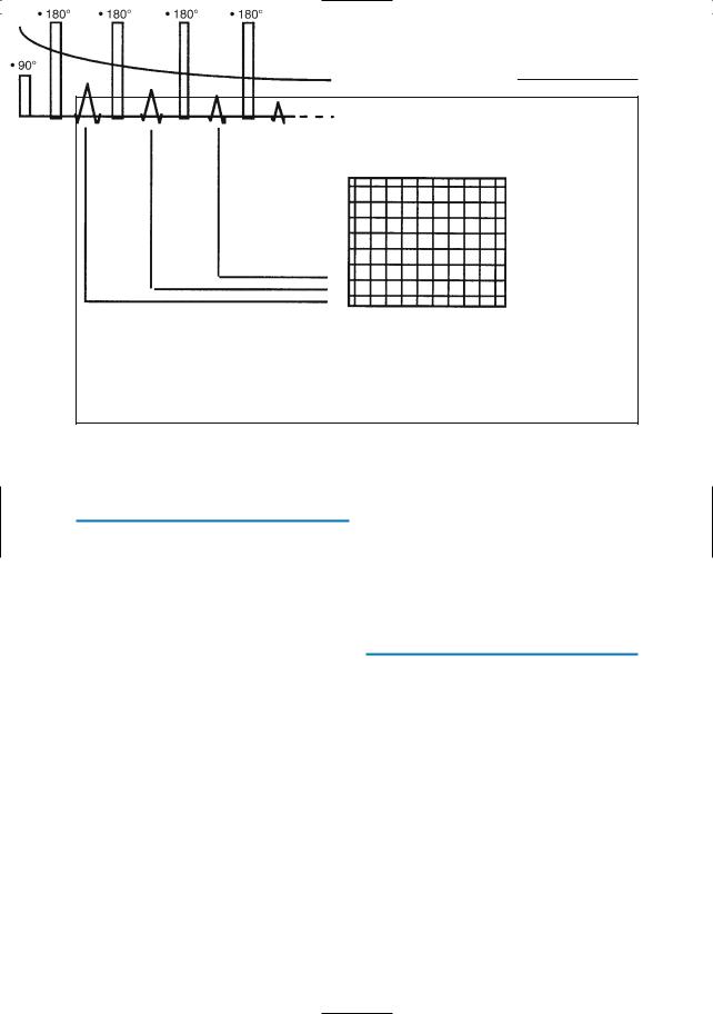
If multiple echoes are generated after a single 90° excitation pulse, each of these echoes fills a horizontal line in the raw data matrix and thus contributes to the image (Fig. I.3). If all the information required to calculate an image is obtained after one single 90° pulse,the technique is referred to
as rapid acquisition with relaxation enhancement (RARE) (see #5). In order to allow “snapshot” imaging, the number of echoes is reduced and half-Fourier reconstruction
is used (see #1). If several 90° pulses are used, the technique is called fast spin echo (FSE) or turbo spin echo (TSE). RARE, halfFourier acquisition single-shot turbo spin echo (HASTE), and fast spin echo are usually applied to provide T2-weighted images (see 1–8).
Replacement of the classical 90° flip angle by lower flip angles is used in a fast technique called gradient echo MRI. The rationale of using lower flip angles is that a (nonlinear) relationship exists between the flip angle and the lowest possible value for TR: the lower the flip angle, the lower the lowest possible value for TR and the lower the examination time. In clinical practice, gradient echo images are commonly used to provide T1-weighted images. Due to recent technical improvements, acquisition times per slice can be reduced to less than 1 s (snapshot gradient echo, see #9).
4Introduction: Basic Principles of Magnetic Resonance Imaging
Fig. I.3. Data collection in RARE (turbo spin echo, fast spin echo). Unlike in spin echo, more than one echo (inverse V) is obtained after one single 90° pulse; each echo is used to fill one horizontal line of
k-space. The larger the number of echoes after a single 90° pulse, the shorter the scan time. Each echo has a decreasing amplitude, which is represented here by the downward slope of the curve
5Contraindications
for Magnetic Resonance Imaging
In order to avoid acute hazards, patients referred to the MRI department should be questioned for traumatic and surgical ante-
cedents. Absolute contraindications for MRI include the following:
●Electronically, magnetically, and mechanically activated implants, e.g., cardiac pacemakers
●Ferromagnetic implants, particularly some types of intracranial aneurysm clips and some types of heart valves (lists of MR-compatible implants should be consulted in each case)
●Intraocular metallic foreign bodies
Pregnancy is not considered as an absolute contraindication.As yet,there are no known biological effects of MRI on fetuses. It might be prudent, however, to exclude pregnant women during the first 3 months of pregnancy.
Suggested Reading
Hashemi RH, Bradley WG (1997) MRI. The basics. Williams & Wilkins, Baltimore
Horowitz A (1995) MRI physics for radiologists. A visual approach. Springer, Berlin Heidelberg New York
Lufkin RB (1990) The MRI manual.Year Book Medical, Chicago
Westbrook C, Kaut C (1993) MRI in practice. Blackwell Scientific, Oxford

MRCP Technique