


CRANKSHAFT/TRANSMISSION 9-1
Crankshaft/Transmission
Table of Contents
Exploded View................................... |
9-2 |
Specifications .................................... |
9-6 |
Special Tools and Sealant ................. |
9-9 |
Crankcase Splitting............................ |
9-10 |
Crankcase Splitting ...................... |
9-10 |
Crankcase Assembly ................... |
9-10 |
Crankshaft and Connecting Rods...... |
9-13 |
Crankshaft Removal .................... |
9-13 |
Crankshaft Installation ................. |
9-13 |
Connecting Rod Removal............ |
9-13 |
Connecting Rod Installation ......... |
9-13 |
Crankshaft/Connecting Rod |
|
Cleaning .................................... |
9-16 |
Connecting Rod Bend.................. |
9-17 |
Connecting Rod Twist .................. |
9-17 |
Connecting Rod Big End Side |
|
Clearance.................................. |
9-17 |
Connecting Rod Big End Bearing |
|
Insert/Crankpin Wear ................ |
9-18 |
Crankshaft Side Clearance .......... |
9-19 |
Crankshaft Runout....................... |
9-20 |
Crankshaft Main Bearing |
|
Insert/Journal Wear................... |
9-20 |
Starter Motor Clutch .......................... |
9-22 |
Starter Motor Clutch |
|
Removal/Installation.................. |
9-22 |
Starter Motor Clutch Inspection ... |
9-22 |
|
|
Starter Motor Clutch Disassembly |
9-22 |
|
|
Starter Motor Clutch Assembly .... |
9-22 |
|
|
Transmission ..................................... |
9-23 |
|
|
Shift Pedal Removal .................... |
9-23 |
|
|
Shift Pedal Installation ................. |
9-23 |
|
|
External Shift Mechanism |
|
|
|
Removal.................................... |
9-24 |
|
|
External Shift Mechanism |
|
|
|
Installation ................................. |
9-25 |
|
|
External Shift Mechanism |
|
|
|
Inspection.................................. |
9-25 |
|
|
.......Transmission Shaft Removal |
9-26 |
9 |
|
Transmission Shaft Installation .... |
9-26 |
|
|
|
|
||
Transmission Shaft Disassembly. |
9-26 |
|
|
Transmission Shaft Assembly...... |
9-27 |
|
|
Shift Drum and Fork Removal...... |
9-30 |
|
|
Shift Drum and Fork Installation... |
9-30 |
|
|
Shift Drum Disassembly............... |
9-30 |
|
|
Shift Drum Assembly ................... |
9-30 |
|
|
Shift Fork Bending ....................... |
9-31 |
|
|
Shift Fork/Gear Groove Wear ...... |
9-31 |
|
|
Shift Fork Guide Pin/Drum |
|
|
|
Groove Wear............................. |
9-31 |
|
|
Gear Dog and Gear Dog Hole |
|
|
|
Damage..................................... |
9-31 |
|
|

9-2 CRANKSHAFT/TRANSMISSION
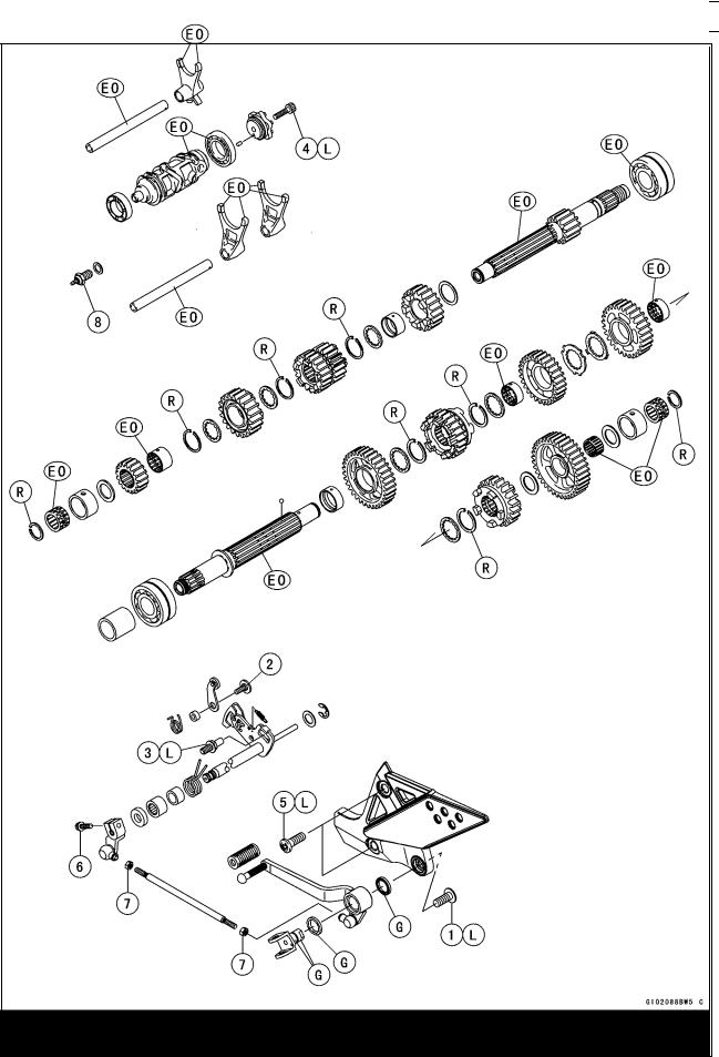
Exploded View

CRANKSHAFT/TRANSMISSION 9-3
Exploded View
|
|
|
|
|
|
|
No. |
Fastener |
|
Torque |
|
Remarks |
|
N·m |
kgf·m |
ft·lb |
||||
|
|
|
||||
1 |
Breather plate bolts |
9.8 |
1.0 |
87 in·lb |
L |
|
2 |
Crankcase bolts (M9, L = 81 mm) |
42 |
4.3 |
31 |
MO, S |
|
3 |
Crankcase bolts (M9, L = 95 mm) |
42 |
4.3 |
31 |
MO, S |
|
4 |
Crankcase bolts (M8) |
27 |
2.8 |
20 |
S |
|
5 |
Crankcase bolts (M7) |
20 |
2.0 |
14 |
S |
|
6 |
Crankcase bolts (M6) |
12 |
1.2 |
104 in·lb |
S |
|
7 |
Starter motor clutch bolts |
12 |
1.2 |
104 in·lb |
L |
|
8 |
Oil pipe holder bolts |
13 |
1.3 |
113 in·lb |
L |
|
9 |
Shift drum bearing holder screw |
5.4 |
0.55 |
48 in·lb |
L |
|
10 |
Shift drum bearing holder bolt |
13 |
1.3 |
113 in·lb |
L |
|
11 |
Connecting rod big end nuts |
see the text |
← |
← |
← |
|
12 |
Crankshaft position rotor bolt |
40 |
4.1 |
30 |
|
|
13 |
Oil pressure switch |
15 |
1.5 |
11 |
SS |
|
14 |
Oil pressure switch terminal bolt |
1.5 |
0.15 |
13 in·lb |
|
|
15 |
Oil passage plugs |
20 |
2.0 |
14 |
L |
|
16 |
Crankshaft sensor cover bolts |
11 |
1.1 |
95 in·lb |
|
17. Do not apply any grease or oil. EO: Apply engine oil.
G: Apply grease.
L: Apply a non-permanent locking agent.
LG: Apply liquid gasket (Kawasaki Bond: 92104–1066).
M: Apply molybdenum disulfide grease.
MO: Apply molybdenum disulfide oil.
(mixture of the engine oil and molybdenum disulfide grease in a weight ratio 10:1) R: Replacement Parts
S: Tightening the fasteners following the specified sequence.
SS: Apply silicone sealant (Kawasaki Bond: 56019–120).
9-4 CRANKSHAFT/TRANSMISSION
Exploded View

CRANKSHAFT/TRANSMISSION 9-5
Exploded View
|
|
|
|
|
|
|
No. |
Fastener |
|
Torque |
|
Remarks |
|
N·m |
kgf·m |
ft·lb |
||||
|
|
|
||||
1 |
Shift pedal mounting bolt |
34 |
3.5 |
25 |
L |
|
2 |
Gear positioning lever bolt |
12 |
1.2 |
104 in·lb |
|
|
3 |
Shift shaft return spring pin |
29 |
3.0 |
22 |
L |
|
4 |
Shift drum cam holder bolt |
12 |
1.2 |
104 in·lb |
L |
|
5 |
Footpeg bracket bolts |
34 |
3.5 |
25 |
L |
|
6 |
Shift lever bolt |
6.9 |
0.70 |
61 in·lb |
|
|
7 |
Tie-rod locknuts |
6.9 |
0.70 |
61 in·lb |
|
|
8 |
Neutral switch |
15 |
1.5 |
11 |
|
EO: Apply engine oil.
G: Apply grease.
L: Apply a non-permanent locking agent.
R: Replacement Parts

9-6 CRANKSHAFT/TRANSMISSION
Specifications
|
|
|
|
|
|
|
Item |
|
|
|
|
Standard |
Service Limit |
Crankshaft, Connecting Rods: |
|
|
|
|
|
|
Connecting rod bend |
|
|
|
|
– – – |
TIR 0.2/100 mm |
|
|
|
|
|
|
(0.008/3.94 in.) |
Connecting rod twist |
|
|
|
|
– – – |
TIR 0.2/100 mm |
|
|
|
|
|
|
(0.008/3.94 in.) |
Connecting rod big end side clearance |
0.13 0.38 mm |
0.58 mm |
||||
|
|
|
|
(0.0051 |
0.0150 in.) |
(0.023 in.) |
Connecting rod big end bearing insert/crankpin |
0.041 0.071 mm |
0.11 mm |
||||
clearance |
|
|
|
(0.0016 |
0.0028 in.) |
(0.0043 in.) |
Crankpin diameter: |
|
|
|
34.984 |
35.000 mm |
34.97 mm |
|
|
|
|
(1.3773 |
1.3780 in.) |
(1.3768 in.) |
Marking |
None |
34.984 |
34.992 mm |
– – – |
||
|
|
|
|
(1.3773 |
1.3776 in.) |
|
|
|
|
|
34.993 |
35.000 mm |
– – – |
|
|
|
|
|||
|
|
|
|
(1.3777 |
1.3780 in.) |
|
Connecting rod big end inside diameter: |
38.000 |
38.016 mm |
– – – |
|||
|
|
|
|
(1.4961 |
1.4967 in.) |
|
Marking |
None |
38.000 |
38.008 mm |
– – – |
||
|
|
|
|
(1.4961 |
1.4964 in.) |
|
|
|
|
|
38.009 |
38.016 mm |
– – – |
|
|
|
|
|||
|
|
|
|
(1.4964 |
1.4967 in.) |
|
Connecting rod big end bearing insert thickness: |
|
|
|
|||
|
Brown |
1.475 1.480 mm |
– – – |
|||
|
|
|
|
(0.05807 0.05827 in.) |
|
|
|
Black |
1.480 1.485 mm |
– – – |
|||
|
|
|
|
(0.05827 0.05846 in.) |
|
|
|
Blue |
1.485 1.490 mm |
– – – |
|||
|
|
|
|
(0.05846 0.05866 in.) |
|
|
Connecting rod big end bearing insert selection:
|
|
|
|
|
|
|
|
|
|
|
|
|
|
|
Con-rod Big End |
|
Crankpin |
|
Bearing Insert |
|
|||||||
|
Bore Diameter |
|
Diameter |
|
|
|
|
|
|
||||
|
Marking |
|
Marking |
|
Size Color |
|
Part Number |
|
|||||
|
None |
|
|
|
|
|
Brown |
|
92139–1110 |
|
|||
|
|
|
|
|
|
|
|||||||
|
|
|
|
|
|
|
|
|
|
|
|
||
|
None |
|
None |
|
Black |
|
92139–1109 |
|
|||||
|
|
|
|
|
|
|
|
|
|
|
|
||
|
|
|
|
|
|
|
|
|
|
|
|
|
|
|
|
|
|
|
|
|
|
|
|
|
|
||
|
|
|
|
|
None |
|
Blue |
|
92139–1108 |
|
|||
|
|
|
|
|
|
|
|||||||
|
|
|
|
|
|
|
|
|
|
|
|
|
|
|
|
|
|
|
|
|
|
|
|
||||
Connecting Rod Bolt Stretch: |
|
|
|
|
|
|
|
|
|
||||
|
|
(Usable Range) |
|
|
|
|
|
|
|||||
|
New connecting rod |
|
0.24 0.36 mm |
|
– – – |
|
|||||||
|
|
|
|
|
|
|
|
|
(0.0094 0.0142 in.) |
|
|
|
|
|
Used connecting rod |
|
0.20 0.32 mm |
|
– – – |
|
|||||||
|
|
|
|
|
|
|
|
|
(0.0079 0.0126 in.) |
|
|
|
|
CRANKSHAFT/TRANSMISSION 9-7
Specifications
|
|
|
|
|
|
|
Item |
|
|
|
|
Standard |
Service Limit |
Crankshaft side clearance |
|
|
|
0.05 0.20 mm |
0.40 mm |
|
|
|
|
|
(0.0020 |
0.0079 in.) |
(0.0157 in.) |
Crankshaft runout |
|
|
|
TIR 0.02 mm (0.0008 in.) or |
TIR 0.05 mm |
|
|
|
|
|
less |
|
(0.0020 in.) |
Crankshaft main bearing insert/journal clearance |
0.020 0.044 mm |
0.07 mm |
||||
|
|
|
|
(0.0008 |
0.0017 in.) |
(0.0028 in.) |
Crankshaft main journal diameter: |
|
|
|
32.984 |
33.000 mm |
32.96 mm |
|
|
|
|
(1.2986 |
1.2992 in.) |
(1.2976 in.) |
Marking |
None |
32.984 |
32.992 mm |
– – – |
||
|
|
|
|
(1.2986 |
1.2989 in.) |
|
|
1 |
|
32.993 |
33.000 mm |
– – – |
|
|
|
|
|
(1.2989 |
1.2992 in.) |
|
Crankcase main bearing inside diameter: |
36.000 |
36.016 mm |
– – – |
|||
|
|
|
|
(1.4173 |
1.4179 in.) |
|
Marking |
|
|
|
36.000 |
36.008 mm |
– – – |
|
|
|
||||
|
|
|
|
(1.4173 |
1.4176 in.) |
|
|
None |
36.009 |
36.016 mm |
– – – |
||
|
|
|
|
(1.4177 |
1.4179 in.) |
|
Crankshaft main bearing insert thickness: |
|
|
|
|||
|
Brown |
1.490 1.494 mm |
– – – |
|||
|
|
|
|
(0.0587 |
0.0588 in.) |
|
|
Black |
1.494 1.498 mm |
– – – |
|||
|
|
|
|
(0.0588 |
0.0590 in.) |
|
|
Blue |
1.498 1.502 mm |
– – – |
|||
|
|
|
|
(0.0590 |
0.0591 in.) |
|
|
|
|
|
|
|
|
|
|
|
Crankshaft main bearing insert selection: |
|
|
|
|
|
||||
|
|
|
|
|
|
|
|
|
|
|
Crankcase Main |
Crankshaft Main |
|
|
Bearing Insert* |
|
|
||
|
Bearing Inside |
Journal Diameter |
|
|
|
|
|
||
|
Diameter Marking |
Marking |
|
Size Color |
Part Number |
Journal Nos. |
|||
|
|
|
|
1 |
|
Brown |
92028–1868 |
3, 5 |
|
|
|
|
|
|
|||||
|
|
|
|
|
|
|
|
|
|
|
|
|
|
|
|
|
92028–1829 |
1, 2, 4 |
|
|
None |
1 |
|
Black |
92028–1867 |
3, 5 |
|
||
|
|
|
|
None |
|
|
92028–1828 |
1, 2, 4 |
|
|
|
|
|
|
|
|
|||
|
|
|
|
|
|
|
|
||
|
None |
None |
|
Blue |
92028–1866 |
3, 5 |
|
||
|
|
|
|
|
|
|
92028–1827 |
1, 2, 4 |
|
*The bearing inserts for Nos. 1, 2 and 4 journals have an oil groove, respectively.
|
|
|
|
|
Transmission: |
|
|
|
|
Shift fork ear thickness |
5.9 6.0 mm |
5.8 mm |
||
|
(0.232 |
0.236 in.) |
(0.228 |
in.) |
Gear groove width |
6.05 6.15 mm |
6.25 mm |
||
|
(0.238 |
0.242 in.) |
(0.246 |
in.) |
|
|
|
|
|

9-8 CRANKSHAFT/TRANSMISSION
Specifications
|
|
|
|
||
Item |
|
Standard |
Service Limit |
||
Shift fork guide pin diameter |
6.9 7.0 mm |
6.8 |
mm |
||
|
(0.272 |
0.276 in.) |
(0.268 |
in.) |
|
Shift drum groove width |
7.05 7.20 mm |
7.3 |
mm |
||
|
(0.278 |
0.283 in.) |
(0.287 |
in.) |
|