


CRANKSHAFT/TRANSMISSION 9-21
Crankshaft and Connecting Rods
•Measure the main bearing inside diameter, and mark the upper crankcase half in accordance with the inside diameter.
Crankcase Main Bearing Inside Diameter Marks : " "
• or no mark.
Tighten the crankcase bolts to the specified torque (see
Crankcase Assembly).
NOTE
○The mark already on the upper crankcase half should almost coincide with the measurement.
Crankcase Main Bearing Inside Diameter Marks |
||||
|
|
36.000 |
36.008 mm (1.4173 |
1.4176 in.) |
|
|
|||
None 36.009 |
36.016 mm (1.4177 |
1.4179 in.) |
||
•Select the proper bearing insert [A] in accordance with the combination of the crankcase and crankshaft coding. Size Color [B]
Crankcase Main |
Crankshaft Main |
|
Bearing Insert* |
|
|||
Bearing Inside |
Journal Diameter |
|
|
||||
|
|
|
|||||
Diameter Marking |
Marking |
Size Color |
Part Number |
Journal Nos. |
|||
|
|
|
1 |
Brown |
92028–1868 |
3, 5 |
|
|
|
|
92028–1829 |
1, 2, 4 |
|||
|
|
|
|
|
|||
None |
1 |
Black |
92028–1867 |
3, 5 |
|||
|
|
|
None |
|
92028–1828 |
1, 2, 4 |
|
|
|
|
|
||||
|
|
|
|
|
|
|
|
None |
None |
Blue |
92028–1866 |
3, 5 |
|||
92028–1827 |
1, 2, 4 |
||||||
|
|
|
|
|
|||
*The bearing inserts for Nos. 1, 2 and 4 journals have an oil groove, respectively.
•Install the new inserts in the crankcase halves and check insert/journal clearance with the plastigage.
9-22 CRANKSHAFT/TRANSMISSION
Starter Motor Clutch
Starter• Motor Clutch Removal/Installation
Refer to the Alternator Rotor Removal and Installation in the Electrical System chapter.
Starter• Motor Clutch Inspection
Remove:
Alternator Cover (see Electrical System chapter)
• Starter Idle Gear
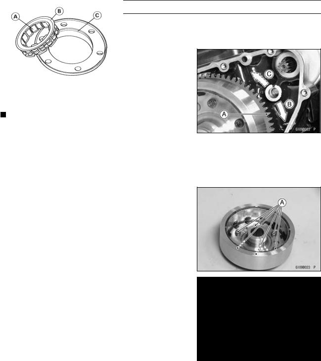
Turn the starter motor clutch gear [A] by hand. The starter motor clutch gear should turn clockwise [B] freely, but should not turn counterclockwise [C].
If the clutch does not operate as it should or if it makes
•noise, go to the next step.
Remove and disassemble the starter motor clutch, and visually inspect the clutch parts.
 If there is any worn or damaged part, replace it.
NOTE
○Examine the starter motor clutch gear as well. Replace it if it is worn or damaged.
Starter• Motor Clutch Disassembly
Remove:
Alternator Rotor (see Electrical System chapter) Starter Motor Clutch Bolts [A] and Starter Motor Clutch
Starter• Motor Clutch Assembly
Be sure to install the one-way clutch [A] so that its flange
•[B] fits in the holder recess [C].
Apply a non-permanent locking agent to the threads of the starter motor clutch bolts, and tighten them.
Torque - Starter Motor Clutch Bolts: 12 N·m (1.2 kgf·m, 104 in·lb)

CRANKSHAFT/TRANSMISSION 9-23
Transmission
Shift• Pedal Removal
Mark [A] the position of the shift lever [B] on the shift shaft
•so that it can be installed later in the same position. Remove:
Shift Lever Bolt [C]
Shift Lever
•Remove:Footpeg Bracket Bolts [A]
Footpeg Bracket [B]
•Remove the bolt [A], footpeg [B] and shift pedal [C].
Shift• Pedal Installation
•Apply grease to the oil seal lip.
Press the oil seals [A] in the shift pedal housing [B] so that the oil seal surfaces are flush with the housing end [C] as shown.
•Apply grease to the sliding surfaces [A] on the footpeg
•holder [B].
Apply a non-permanent locking agent to the shift pedal
•mounting bolt [C]. Tighten:
Torque - Shift Pedal Mounting Bolt: 34 N·m (3.5 kgf·m, 25 ft·lb)
Footpeg Bracket [D]
Shift Pedal [E]
Oil Seals [F]

9-24 CRANKSHAFT/TRANSMISSION
Transmission
•Install the footpeg bracket [A].
•Tighten:
Torque - Footpeg Bracket Bolts [B]: 34 N·m (3.5 kgf·m, 25 ft·lb)
•Install the shift lever [A], aligning the mark (previously
•marked). Tighten:
•Torque - Shift Lever Bolt: 6.9 N·m (0.70 kgf·m, 61 in·lb)
Install the shift pedal [B] as shown.
About 90° [C]
○To adjust the pedal position, loosen the front locknut [D] (left-hand threads) and rear locknut [E] and then turn the
•tie-rod [F]. Tighten:
Torque - Tie-rod Locknuts: 6.9 N·m (0.70 kgf·m, 61 in·lb)
External• Shift Mechanism Removal
Remove:
Engine Oil (drain, see Engine Lubrication System chapter)
Shift Pedal (see Shift Pedal Removal)
Clutch (see Clutch chapter)
Oil Pipe Holder Bolts [A]
Oil Pipe Holders [B], Oil Pipe [C] and O-rings
•Remove the shift shaft assembly [A] while pulling the shift mechanism arm [B] to the direction of the arrow.

CRANKSHAFT/TRANSMISSION 9-25
Transmission
•Remove:
Gear Positioning Lever Bolt [A]
Gear Positioning Lever [B], Collar and Spring
External• Shift Mechanism Installation
Install the gear positioning lever [A] as shown.
Spring [B]
Collar [C]
• Bolt [D]
Tighten:
Torque - Gear Positioning Lever Bolt: 12 N·m (1.2 kgf·m,
• 104 in·lb)
•Apply grease to the O-rings on the oil pipe ends.
Apply a non-permanent locking agent to the oil pipe holder bolts and tighten them.
Torque - Oil Pipe Holder Bolts: 13 N·m (1.3 kgf·m, 113 in·lb)
External• Shift Mechanism Inspection
Examine the shift shaft [A] for any damage.
If the shaft is bent, straighten or replace it.
If the serration [B] are damaged, replace the shaft.
If the springs [C] are damaged in any way, replace them. If the shift mechanism arm [D] is damaged in any way, replace the arm.
•Check the return spring pin [A] is not loose.
If it is loose, unscrew it, apply a non-permanent locking agent to the threads, and tighten it.
•Check the gear positioning lever [B] and its spring for breaks or distortion.
If the lever or spring are damaged in any way, replace
•them.
Visually inspect the shift drum cam [C].
If they are badly worn or if they show any damage, replace it.

9-26 CRANKSHAFT/TRANSMISSION
Transmission
Transmission• Shaft Removal
•Split the crankcase (see Crankcase Splitting). Remove the drive shaft [A] and output shaft [B].
Transmission• Shaft Installation
Check to see that the set pins [A] and set rings [B] are in place.
•Install the drive shaft and output shaft into the upper
•crankcase half.
Apply engine oil to the bearings.
○The bearing set pins and rings must match properly with the holes or grooves in the bearing outer races. When they are properly matched, there is no clearance [A] between the crankcase and the bearing outer races.
•Assemble the crankcase.
•Press in the oil seal [A] onto collar [B] so that the surface of the oil seal is flush with the counterbore bottom surface
[C]of the crankcase.
Transmission• Shaft Disassembly
Remove the transmission shafts (see Transmission Shaft
•Removal).
Remove the circlips, disassemble the transmission
•shafts.
The 5th gear [A] on the output shaft has three steel balls assembled into it for the positive neutral finder mechanism. Remove the 5th gear.
○Set the output shaft in a vertical position holding the 3rd gear [B].
○Spin the 5th gear quickly [C] and pull it off upward.
CRANKSHAFT/TRANSMISSION 9-27
Transmission
•Remove the ball bearing [A] from each shafts.
Special Tools - Bearing Puller: 57001–135 [B] Bearing Puller Adapter: 57001–317 [C]
•Discard the bearing.
Transmission• Shaft Assembly
•Apply engine oil to the bushings, ball bearings and shafts. Install the gear bushings [A] on the shaft with their holes [B] aligned.
•Replace any circlips removed with new ones.
•Install the circlips [A] so that the opening [B] is aligned with a spline groove [C].
•The drive shaft gears can be recognized by size: the gear with the smallest diameter is 1st gear, and the largest one is 6th gear. Be sure that all parts are put back in the correct sequence and all circlips and washers are properly in
•place.
Install the 3rd/4th gear onto the drive shaft with their oil
•holes aligned.
Install the 6th gear bushing onto the drive shaft with their
•oil holes aligned.
The output shaft gears can be recognized by size: the gear with the largest diameter is 1st gear, and the smallest one is 6th gear. Be sure that all parts are put back in the correct sequence and all circlips and washers are
•properly in place.
Install the 5th and 6th gears onto the output shaft with
•their oil holes aligned.
Install the 3rd/4th gear bushings onto the output shaft with their oil holes aligned.

9-28 CRANKSHAFT/TRANSMISSION
Transmission
NOTE
○When the toothed washers [28] [29] are assembled onto the output shaft, note the following.
○When the tangs [A] of the toothed washer [29] shall be assembled, they should be installed into the notch [B] of the toothed washer [28] (see Page 9–29).
•Fit the steel balls into the 5th gear holes in the output shaft, aligning three oil holes [D].
5th Gear [A] Output Shaft [B] Steel Balls [C]
CAUTION
Do not apply grease to the balls to hold them in place. This will cause the positive neutral finder mechanism to malfunction.
○After assembling the 5th gear with steel balls in place on the output shaft, check the ball-locking effect that the 5th gear doesn’t come out of the output shaft when moving it
•up and down by hand.
Check that each gear spins or slides freely on the transmission shafts without binding after assembly.

CRANKSHAFT/TRANSMISSION 9-29
Transmission
|
|
|
|
|
|
|
|
|
|
|
|
|
|
|
|
|
|
|
|
|
|
|
|
1. |
1st Gear |
|
|
|
18. |
Bushing |
|
|
|
||
2. |
2nd Gear |
|
|
|
19. |
Bushing |
|
|
|
||
3. |
3rd Gear |
|
|
|
20. |
Circlip |
|
|
|
||
4. |
4th Gear |
|
|
|
21. |
Ball Bearing |
|
|
|
||
5. |
5th Gear |
|
|
|
22. |
Collar |
|
|
|
||
6. |
6th (Top) Gear |
|
|
|
23. |
Washer |
|
|
|
||
7. |
Toothed Washer, |
|
|
31 mm (1.22 in.) |
24. |
Toothed Washer |
|
|
|
||
|
|
|
|
|
|||||||
8. |
Thrust Washer, |
|
|
30 mm (1.18 in.) |
25. |
Oil Seal |
|
|
|
||
|
|
|
|
|
|||||||
9. |
Circlip |
|
|
|
|
26. |
Thrust Washer, |
|
31 mm |
||
|
|
|
|
|
|||||||
10. |
Circlip |
|
|
|
|
(1.22 in.) |
|
|
|
|
|
11. |
Bushing |
|
|
|
27. |
Thrust Washer, |
|
33 mm |
|||
|
|
|
|
||||||||
12. |
Bushing |
|
|
|
|
(1.30 in.) |
|
|
|
|
|
13. |
Needle Bearing |
|
|
|
28. |
Toothed Washer |
|
|
|
||
14. |
Needle Bearing |
|
|
|
29. |
Toothed Washer |
|
|
|
||
15. Bearing Outer Race |
30. |
Toothed Washer, |
|
|
35 mm |
||||||
|
|
||||||||||
16. |
Steel Ball |
|
|
|
|
(1.38 in.) |
|
|
|
||
17. |
Nut |
|
|
|
|
|
|
|
|
|
|

9-30 CRANKSHAFT/TRANSMISSION
Transmission
Shift• Drum and Fork Removal
Remove:
Lower Crankcase Half (see Crankcase Splitting)
Transmission Shafts
External Shift Mechanism (see External Shift Mechanism Removal)
Bolt [A] and Screw [B]
• Shift Drum Bearing Holder [C]
•Pull out the shift rods [D], and take off the shift forks. Pull out the shift drum [E].
Shift• Drum and Fork Installation
Install the shift rods [A], noting the groove position. The
•rods are identical.
Position the one with shortest ears [B] on the drive shaft and place the pin in the center groove in the shift drum [C].
○•The two forks [D] on the output shaft are identical. Install the forks so that its “266” and “267” side faces
•clutch side.
Apply a non-permanent locking agent to the threads of the shift drum bearing holder bolt and screw, and tighten them.
Torque - Shift Drum Bearing Holder Bolt: 13 N·m (1.3 kgf·m, 113 in·lb)
Shift Drum Bearing Holder Screw: 5.4 N·m (0.55 kgf·m, 48 in·lb)
Shift• Drum Disassembly
Remove the shift drum (see Shift Drum and Fork Re-
•moval).
While holding the shift drum with a vise, remove the shift drum cam holder bolt.
Shift Drum Cam Holder Bolt [A]
Dowel Pin [B]
Shift• Drum Assembly
•Be sure to install the dowel pin.
Apply a non-permanent locking agent to the threads of the shift drum cam holder bolt, and tighten it.
Torque - Shift Drum Cam Holder Bolt: 12 N·m (1.2 kgf·m, 104 in·lb)